Foldable drain pipe for a decanter in a water treatment system

a water treatment system and drain pipe technology, applied in the direction of liquid displacement, separation processes, bends, etc., can solve the problems of inrush risk immediate plugging, damage to the hose, and disturb the settled bod sludg

Inactive Publication Date: 2016-06-09
CLEARCOVE SYST
View PDF2 Cites 3 Cited by
  • Summary
  • Abstract
  • Description
  • Claims
  • Application Information

AI Technical Summary

Benefits of technology

[0017]An FDP for draining effluent from the decanter in accordance with the present invention comprises a plurality of pipe sections sealingly and rotatably connected together end to end by elbow coupling pairs and rotary seals to form an articulated drain pipe that can varyingly fold to accommodate changes in the vertical position of the decanter. One of multiple hobble apparatus options attached to various of the pipe sections prevents rotational hyperextension of any of the elbow coupling pairs beyond 180° to assure that the pipe always re-folds correctly, as desired.

Problems solved by technology

Second, it must fold into a compact space as the decanter reaches the bottom of its travel.
Third, it must not contact the sides of the tank because this would both disturb the settled BOD sludge and potentially. damage the hose.
Fourth, the hose must be strong enough to support its own weight, even when suspended above the water surface and filled with water as can occur during maintenance or cleaning.
Such an inrush risks immediate plugging of the decanter screens by solid materials which otherwise would float and be skimmed off or would settle before reaching the decanter.
In practice it is difficult for a flexible hose or rigid pipe or other alternative means to meet all of these requirements: a conventional prior art flexible hose, as disclosed in incorporated U.S. application Ser. No. 14 / 142,197, can contact the tank wall and may not be sufficiently strong to support its weight when filled with fluid; a telescoping pipe does not enable sufficient vertical range of travel of an SBX; and a tilting pipe, also as disclosed in U.S. application Ser. No. 14 / 142,197, requires the length of its tilt arm to pivot along the tank's horizontal axis and thus would reduce the possible number of decanters.

Method used


Image

  • Foldable drain pipe for a decanter in a water treatment system
  • Foldable drain pipe for a decanter in a water treatment system
  • Foldable drain pipe for a decanter in a water treatment system

Examples


Embodiment Construction

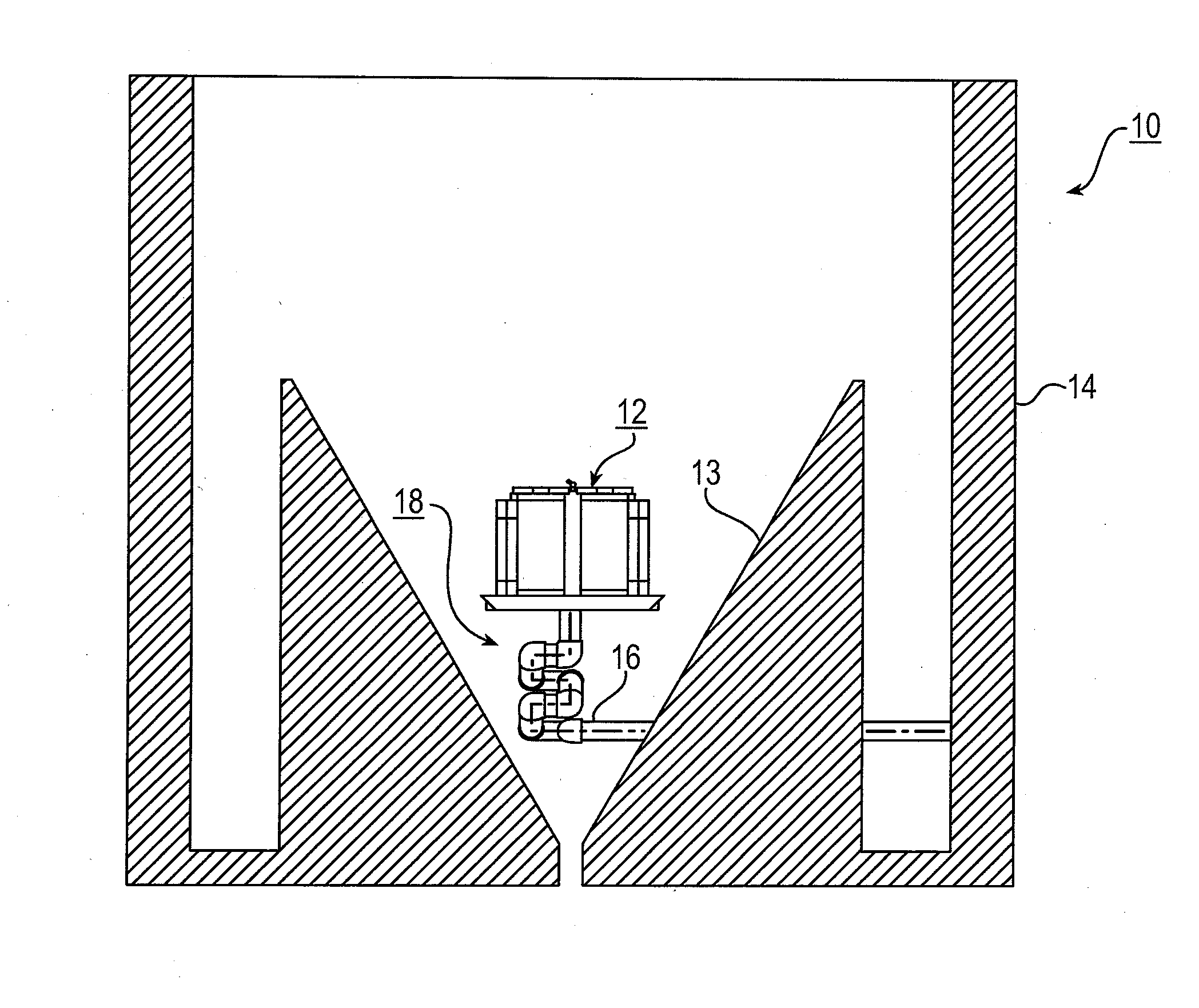
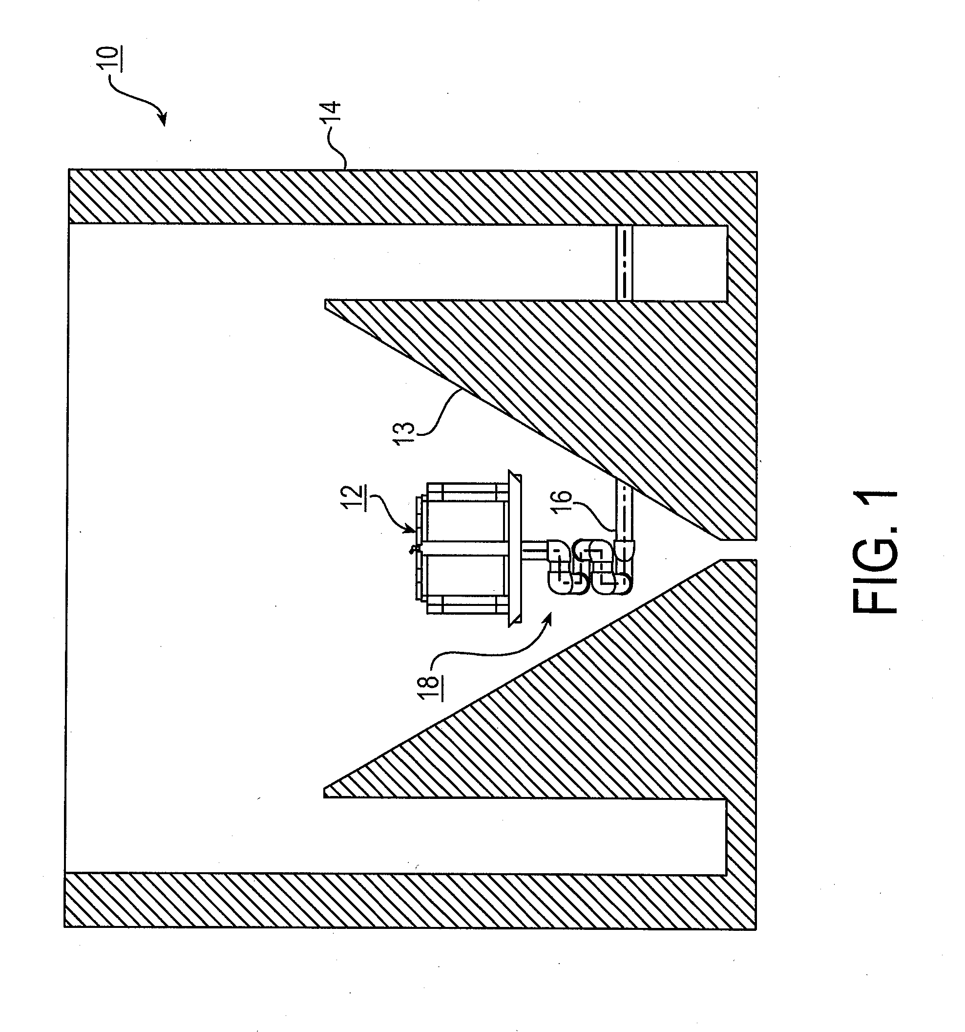
[0026]Referring to FIG. 1, there is shown a decanter system 10 in accordance with the present invention, comprising a first embodiment of a decanter 12, a settling tank 14 having a tank outlet 16, and a foldable drain pipe (FDP) 18 connected therebetween. Preferably, tank outlet 16, extending through-the wall of tank 14, is directly below the vertical operational path of the decanter such that FDP 18 folds and unfolds beneath decanter 12 and above tank outlet 16.

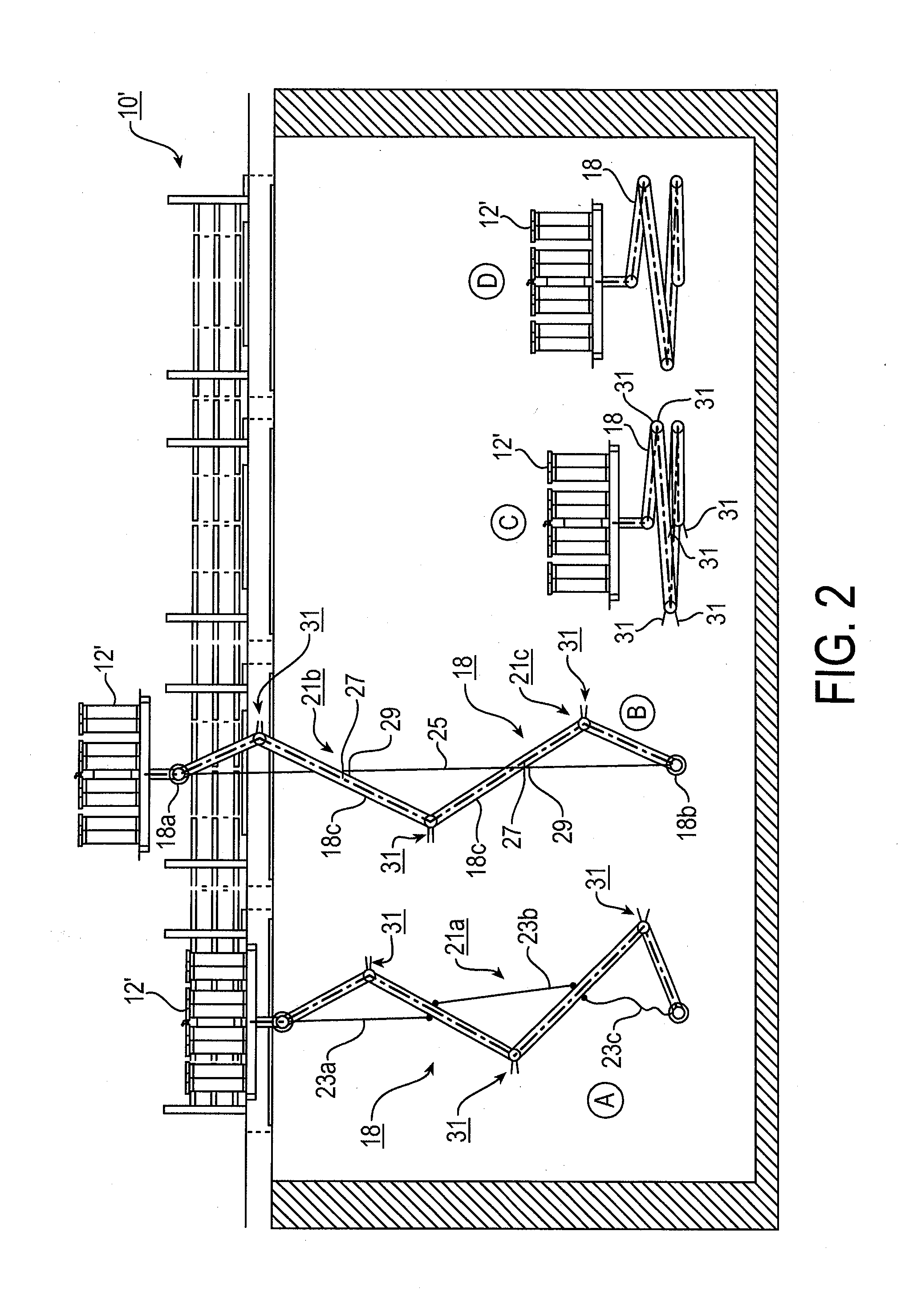
[0027]Referring to FIG. 2, in a schematic decanter system 10′, an embodiment of a vertical lift decanter 12′ and associated FDP 18 are shown in four separate positions: A) flushing and cleaning of the decanter above the tank with FDP 18 partially unfolded; B) maintenance of the decanter above the tank with FDP 18 fully unfolded but hobbled; C) tank empty with the decanter fully lowered and FDP 18 fully folded; and D) the decanter in an intermediate operating position with FDP 18 partially unfolded. It will be seen that in al...


PUM

PropertyMeasurementUnit
angleaaaaaaaaaa
volumeaaaaaaaaaa
temperatureaaaaaaaaaa

Abstract

A foldable drain pipe for draining effluent from a decanter in a settling tank in a water treatment system, comprising a plurality of pipe sections sealingly connected together end to end by pivotable elbow coupling pairs to form an articulated drain foldable in a vertical direction. The drain pipe is attachable at an upper end to the decanter and at a lower end to a tank outlet in the tank wall. The drain pipe can support its own weight and cannot come into contact undesirably with any other portion of the tank wall. The pipe unfolds upward as needed when the decanter and effluent level are high, and folds compactly between the decanter and the tank outlet when the decanter and effluent level are low. Multiple hobble apparatus options may be selected as defined herein to prevent rotational hyperextension of any of the elbow coupling pairs to assure that the pipe folds correctly.

Description

RELATIONSHIP TO OTHER APPLICATIONS AND PATENTS[0001]This application is a Continuation-In-Part of a pending U.S. patent application Ser. No. 14 / 142,197, filed Dec. 27, 2013, entitled “Method and apparatus for a vertical lift decanter system in a water treatment system”, which is herein incorporated by reference in its entirety.FIELD OF THE INVENTION[0002]The present invention relates generally to the field of settling tanks in water treatment systems wherein grit and dense solids are allowed to settle from the influent, and buoyant solids (fats, oil, grease, non-dense solids) are prevented from entering into an effluent decanter. As used herein, “decanter” should be taken to mean a screen / filter box assembly, also known as an SBX, or a floating weir-like assembly, also known as a DBX, or a hybrid combination of both in a single structure. More particularly, the present invention relates to an effluent decanter in the form of a vertically driven or floating box assembly (BX) for sepa...

Claims


Application Information

Patent Timeline
Patent Type & Authority Applications(United States)
IPC IPC(8): F16L27/08C02F1/00F16L43/00B01D21/24
CPCF16L27/0861B01D21/24C02F2001/007F16L43/00C02F2101/32C02F1/00B01D21/0006B01D21/0012B01D21/2427B01D21/2444B01D21/34
Inventor BUTLER, MICHAEL A.BERTONI, ALFREDJACOBS, JONATHAN M.
Owner CLEARCOVE SYST
Why Eureka
Try Eureka