

Fulcrum Knee Brace
a knee brace and full-length technology, applied in the field of full-length knee braces, can solve the problems that the knee braces do not make allowances for knee cap protection, and achieve the effect of preventing hyperextension of the user's leg, and providing continuous protection from impacts
- Summary
- Abstract
- Description
- Claims
- Application Information
AI Technical Summary
Benefits of technology
Problems solved by technology
Method used
Image

Examples
Embodiment Construction
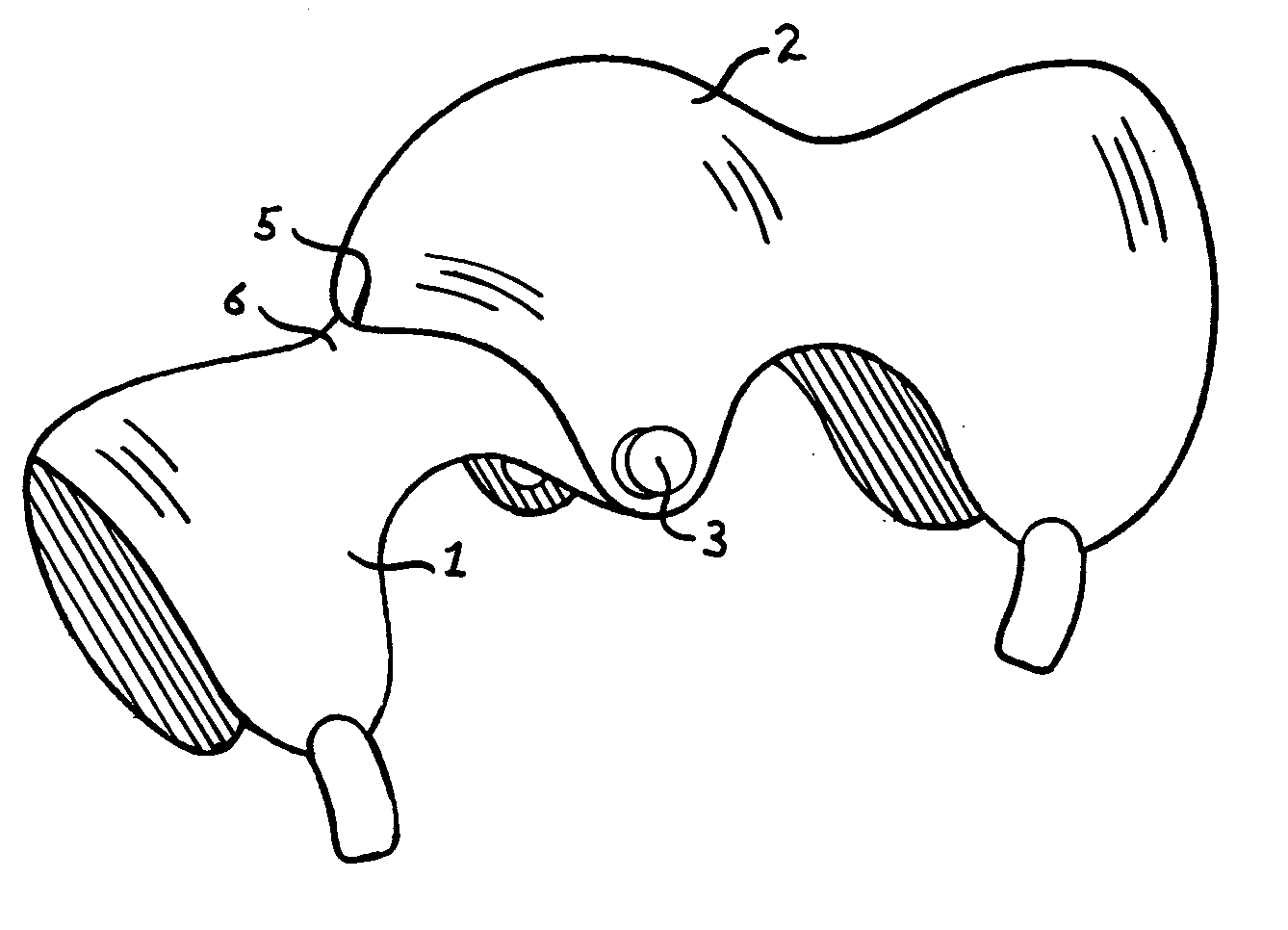
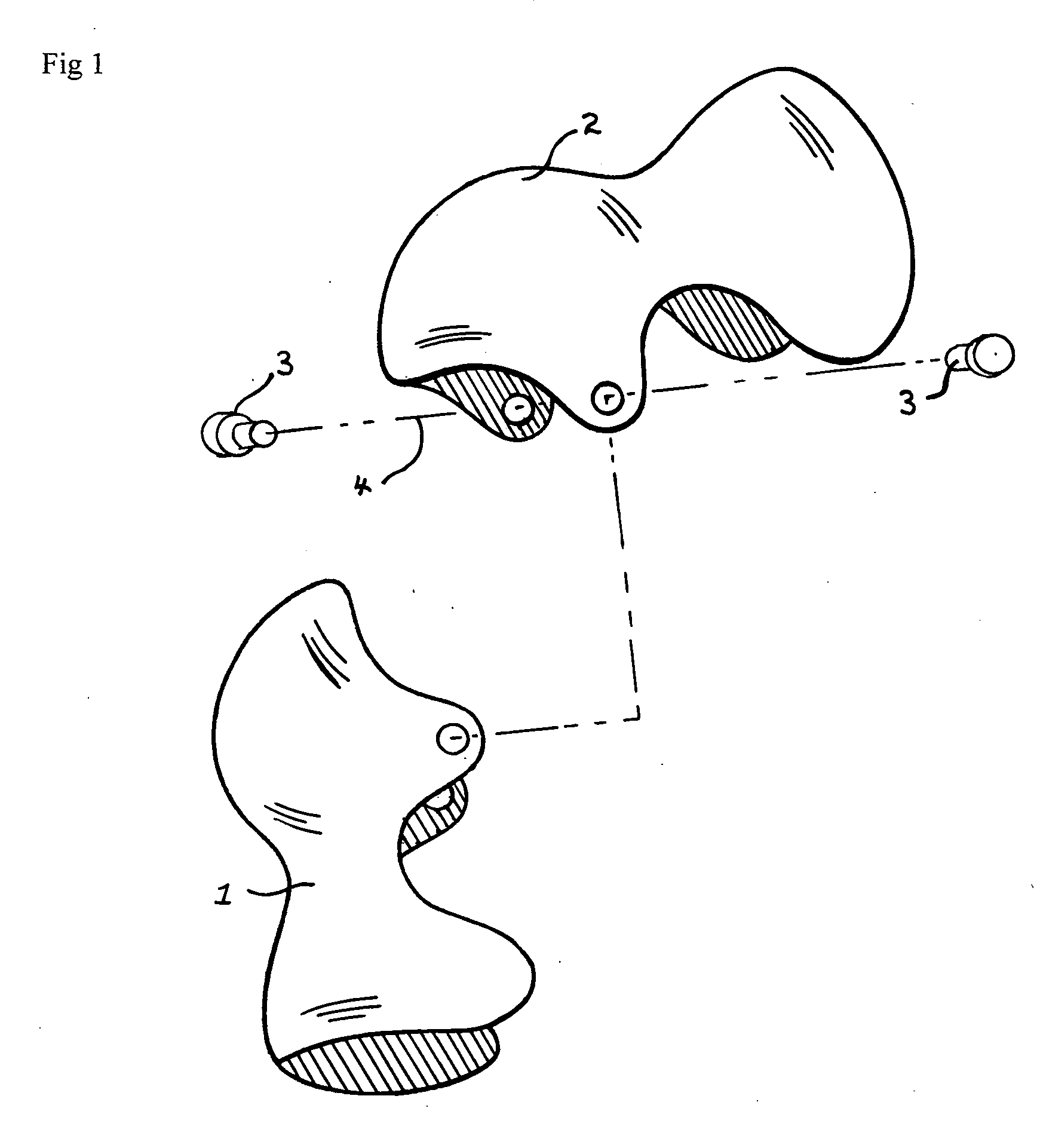
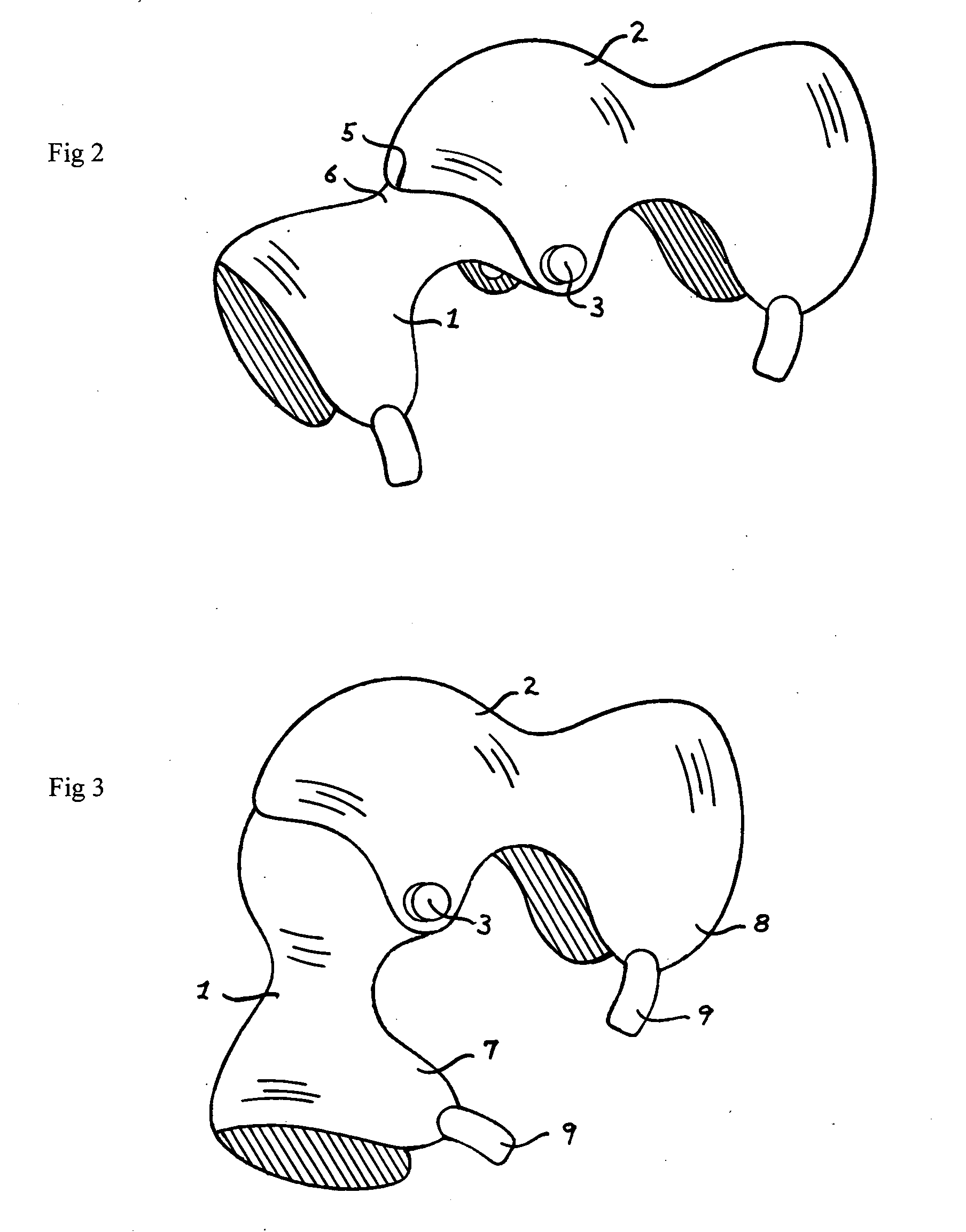
A brace for supporting a knee joint is disclosed which is specifically adapted to restrict lateral movement of the knee joint in addition to preventing hyperextension of the user's leg, while allowing normal movement of the knee joint when the brace is applied to the user's leg. The object of the invention is to provide protection to the ligaments and tendons of the knee joint by limiting the direction and range of movement of the user's leg while the user is engaged in sports related activities or other potentially hazardous activities. The knee brace consists of two separate sections, both comprised of a semi-rigid plastic material of composition such as that which would be commonly used in sports related equipment. The brace is formed by a rigid proximal member that fully covers the front and sides of the knee and extends partially over the tibia. Padding is attached to the inner surface to provide a firm interference between the rigid plastic and the user's leg. The brace furthe...
PUM
 Abstract
Description
Claims
Application Information