Non-contact adjustable hysteretic magnetic encoder

a hysteretic magnetic encoder, non-contact technology, applied in the direction of electrical/magnetically converting sensor output, stray field compensation, instruments, etc., can solve the problem of high manufacturing unexhausted displacement limit and high cost of multi-pole magnetic blocks. , to achieve the effect of high cos

Active Publication Date: 2016-06-09
NAT CHUNG SHAN INST SCI & TECH
View PDF6 Cites 5 Cited by
  • Summary
  • Abstract
  • Description
  • Claims
  • Application Information

AI Technical Summary

Benefits of technology

[0005]It is an objective of the present invention to dispense with a multi-pole magnetic block and thus circumvent the problem with high costs incurred in magnetization of the multi-pole magnetic block.
[0006]Another objective of the present invention is to provide a low-cost encoder.
[0014]Accordingly, the present invention is characterized in that: a low-cost non-contact adjustable hysteretic magnetic encoder is attained by integration of software and hardware, requiring just a magnetic block, two magnetic sensing components, and a controller, so as to bring about a hysteresis effect within a range before and after the turning point of a pulse wave by means of 4-state encoding. Hence, the non-contact adjustable hysteretic magnetic encoder of the present invention dispenses with any multi-pole magnetic block and thus provides the solution to the known problems with magnetization of multi-pole magnetic blocks.
[0016]To meet the requirements of the present invention, it is feasible to adopt a conventional 8-bit or 16-bit micro-control unit (MCU) and thus cut costs greatly by dispensing with any dedicated decoding chip, such as Melexis Triaxis MLX90316.
[0017]In conclusion, a non-contact adjustable hysteretic magnetic encoder of the present invention is characterized in that: the phase difference between a first phase signal and a second phase signal is adjusted, and a hysteresis range, also known as hysteresis angle, is adjusted, according to the grids attributed to the predetermined number of grids before the turning point and the grids attributed to the predetermined number of grids after the turning point. Hence, the non-contact adjustable hysteretic magnetic encoder features enhanced potential of expansion and marked industrial practicability.

Problems solved by technology

However, in the course of its displacement, the multi-pole magnetic block takes a journey which depends on its size, and thus the multi-pole magnetic block is subject to a limit in terms of its unexhausted displacement.
Another drawback of the multi-pole magnetic block is that it is confronted with strict technical requirements of magnetization, thereby leading to high manufacturing costs of the multi-pole magnetic block.
The Hall switch must have a built-in Smith triggering delaying circuit for eliminating jitter which might otherwise occur to digital signal conversion, thereby incurring costs.

Method used


Image

  • Non-contact adjustable hysteretic magnetic encoder
  • Non-contact adjustable hysteretic magnetic encoder
  • Non-contact adjustable hysteretic magnetic encoder

Examples


Embodiment Construction

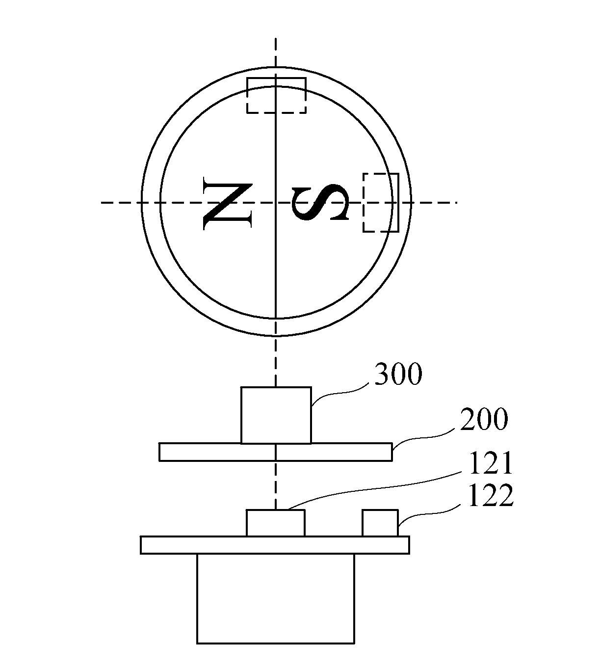
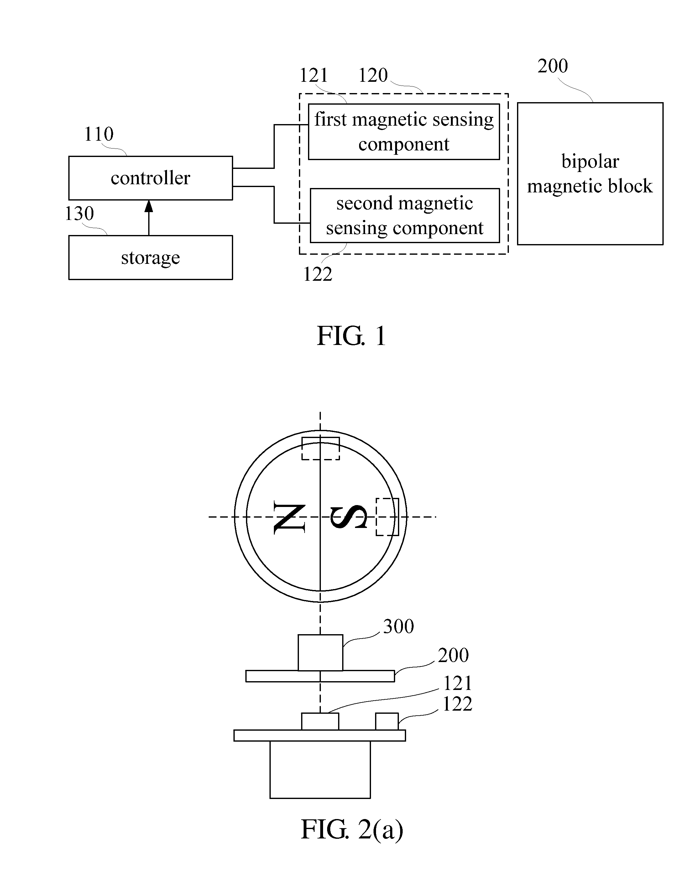
[0025]Referring to FIG. 1, there is shown a function block diagram of a non-contact adjustable hysteretic magnetic encoder according to an embodiment of the present invention. According to the present invention, the non-contact adjustable hysteretic magnetic encoder comprises a bipolar magnetic block 200, two magnetic sensing components 120 (a first magnetic sensing component 121 and a second magnetic sensing component 122), a storage 130, and a controller 110.

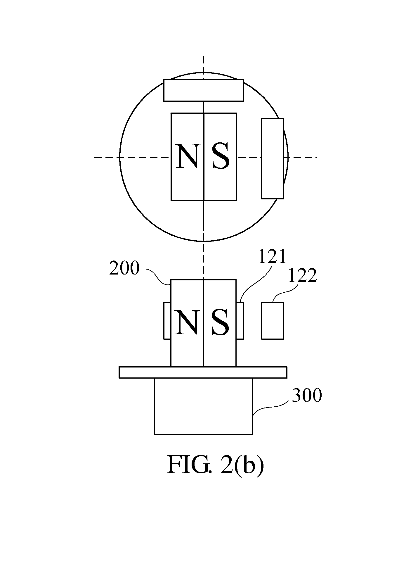
[0026]The bipolar magnetic block 200 is disposed at a rotating shall of a rotation driving apparatus (shown in FIG. 2). The two magnetic sensing components 120 are disposed in the vicinity of the bipolar magnetic block 200 and spaced apart from each other by a predetermined distance, such that it is feasible to generate two induction signals which differ from each other by a first predetermined phase by sensing the magnetic field of the bipolar magnetic block 200.

[0027]The storage 130 stores therein a rotation angle table, a f...


PUM


Abstract

A non-contact adjustable hysteretic magnetic encoder includes a bipolar magnetic block, two magnetic sensing components, a storage, and a controller. After retrieving the current rotation angle by accessing a rotation angle table, the controller determines, by an encoding rule, digital logical values of a first phase signal (A-phase signal) and digital logical values of a second phase signal (B-phase signal) and outputs the digital logical values. The phase difference between a first phase signal and a second phase signal is adjusted, and a hysteresis range, also known as hysteresis angle, is adjusted, according to the grids attributed to the predetermined number of grids before the turning point and the grids attributed to the predetermined number of grids after the turning point. Hence, the non-contact adjustable hysteretic magnetic encoder features enhanced potential of expansion and marked industrial practicability.

Description

FIELD OF TECHNOLOGY[0001]The present invention relates to encoders, and more particularly, to a non-contact adjustable hysteretic magnetic encoder attained by integration of software and hardware.BACKGROUND[0002]A conventional automation system usually has sensors mounted on a rotation shaft or a movement shaft to receive feedback signals pertaining to a rotation speed, a new direction, or a displacement in order to effectuate control. A typical sensing signal sensed with a sensor is usually a voltage signal. To allow the voltage signal to be read by the other digital logical components later, it is usually necessary to convert the voltage signal into a digital pulse signal with an encoding program of an encoder and then convert the digital pulse signal into various control signals with a decoder, a counter, or a frequency counter. Furthermore, the control signals thus generated can be used to detect a rotation speed, a new direction, a location, and an angle.[0003]Conventionally, a...

Claims


Application Information

Patent Timeline
Patent Type & Authority Applications(United States)
IPC IPC(8): G01D5/14G01D18/00
CPCG01D18/00G01D5/142G01D5/145
Inventor WU, RUH-HUACHANG, CHUNG-TSENG
Owner NAT CHUNG SHAN INST SCI & TECH
Why Eureka
Try Eureka