
Segmented-foil divertor

Active Publication Date: 2016-06-09
GX TECH CANADA LTD
View PDF1 Cites 20 Cited by
  • Summary
  • Abstract
  • Description
  • Claims
  • Application Information

AI Technical Summary

Benefits of technology

The present invention provides a collapsible segmented-foil divertor with high efficiency and reduced demand on the tow vessel's handling gear. This is achieved by shortening the length of certain bridle lines using winches to achieve the desired angle and alignment of the divertor.

Problems solved by technology

For very low aspect ratios, such as 1:1 or less, the divertor's lift-to-drag ratio may be in the range of 2:1, which is considered poor.
While high aspect ratio divertors generate high lift for minimal drag, they also present operational challenges in terms of deployment and recovery from the vessel.
Generally, long and narrow divertors tend to be more problematic for handling and stowage than short and wide divertors.
This presents operational challenges for the operator during launch and retrieval of the divertor, particularly in rough sea states.
This results in a heavy divertor that places additional demands on the vessel's handling gear.
For those applications where the divertor is intended to operate near the surface, a heavy divertor also requires a large surface reference float, which increases the drag of the divertor, as well the requirements for handling and stowage.

Method used


Image

  • Segmented-foil divertor
  • Segmented-foil divertor
  • Segmented-foil divertor

Examples


Embodiment Construction

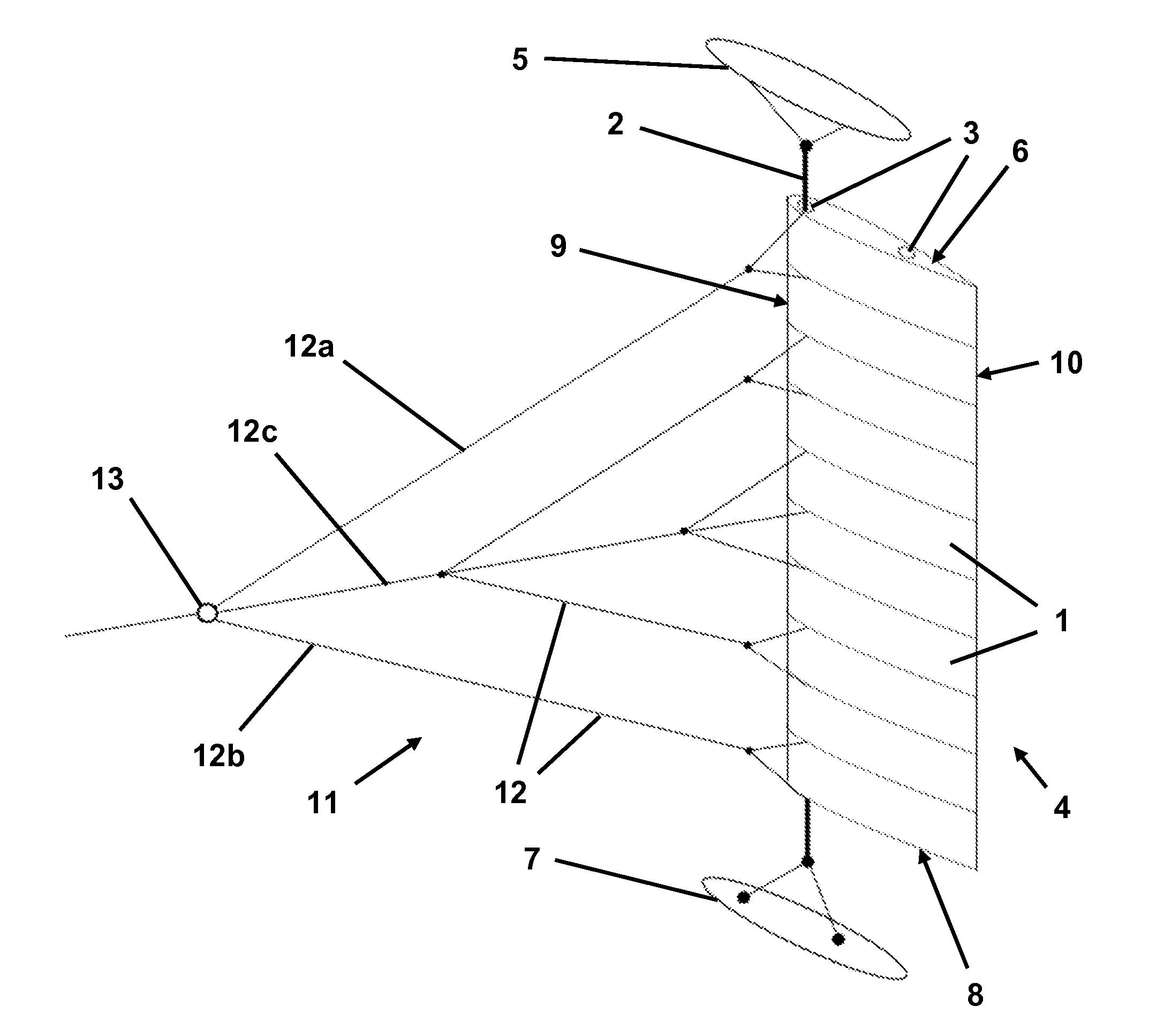
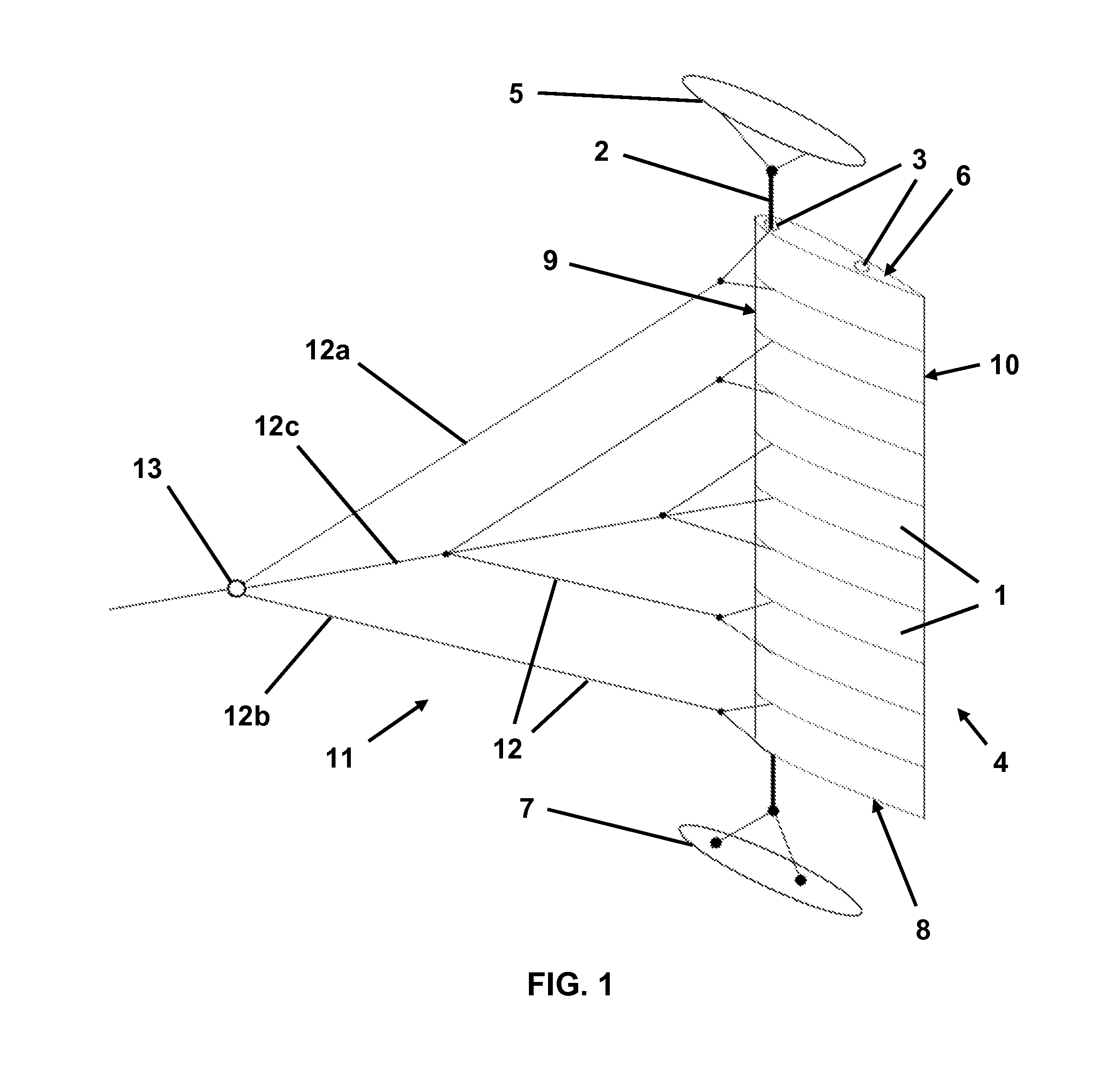
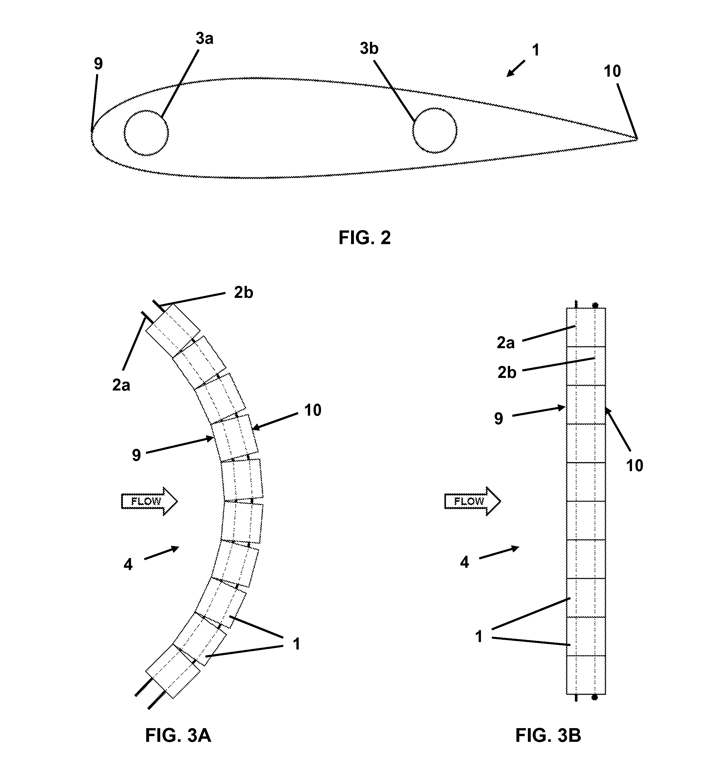
[0037]The collapsible segmented-foil divertor, according to the present invention, provides a high aspect ratio wing, for a high lift-to-drag efficiency, that facilitates the launch, retrieval, handling, and stowage operations associated with tall narrow divertors. This may be achieved, in one embodiment, by a segmented-foil divertor, which comprises a wing having, by way of example a 10 m span and a 1 m chord, yielding an aspect ratio of 10:1. The wing is comprised of individual foil segments 1 stacked end-to-end, for example 10 foil segments 1 each having a 1 m span. The foil segments 1 are held together by at least one rope, or conduit cable 2, which is threaded through an internal conduit 3 in each foil segment 1. When the conduit cable 2 is slack, the end to end assembly, or stack 4, of foil segments is flexible, or collapsible, and can be folded and unfolded on deck and manipulated on deck and over obstructions, and deployed over a bulwark or down a dedicated deployment chute ...


PUM


Abstract

A segmented-foil divertor for marine towed application, such as marine seismic exploration, having a plurality of longitudinally stackable foil segments with an internal conduit extending along the span of each segment to receive a cable passing therethrough.

Description

CROSS-REFERENCE TO RELATED APPLICATION[0001]This application claims the benefit of U.S. provisional application No. 62 / 087,883, which was filed on Dec. 5, 2014, the entirety of which is incorporated herein by reference.FIELD OF THE INVENTION[0002]The invention relates to divertors and method of using divertors for achieving the desired position of various marine towed seismic equipment.BACKGROUND OF THE INVENTION[0003]When towing in-water equipment behind a vessel, such as when conducting seismic surveys, it is desirable that the towed equipment be positioned at some lateral offset, either to port or to starboard, with respect to the track of the vessel. To position, or divert, the towed equipment to one side of the vessel or the other, a device is typically deployed in the water that is capable of generating hydrodynamic lift in a direction that is perpendicular to the direction of travel of the vessel. A number of such devices are known and are variously referred to as “divertors”...

Claims


Application Information

Patent Timeline
IPC IPC(8): G01V1/38B63B22/00B63B21/66
CPCG01V1/3826B63B22/00B63B21/663B63B21/66G01V1/38
Inventor MARTIN, DANIEL GEORGE
Owner GX TECH CANADA LTD
Features
  • Generate Ideas
  • Intellectual Property
  • Life Sciences
  • Materials
  • Tech Scout
  • Unparalleled Data Quality
  • Higher Quality Content
  • 60% Fewer Hallucinations
Learn More