

Image display apparatus
a technology of image display and display device, which is applied in the direction of mechanical devices, static indicating devices, instruments, etc., can solve the problems of inability to meet the requirements of the user, the image display apparatus described in jp-, 78022, etc., and achieve the effect of increasing the beam width (cross-sectional area) of the video light and increasing the visibility of the video ligh
- Summary
- Abstract
- Description
- Claims
- Application Information
AI Technical Summary
Benefits of technology
Problems solved by technology
Method used
Image

Examples
first embodiment
[0041]An image display apparatus according to a first embodiment of the invention will first be described.
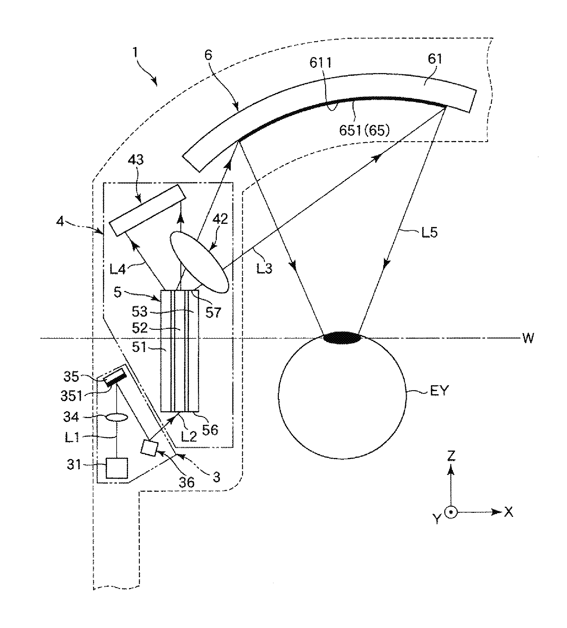
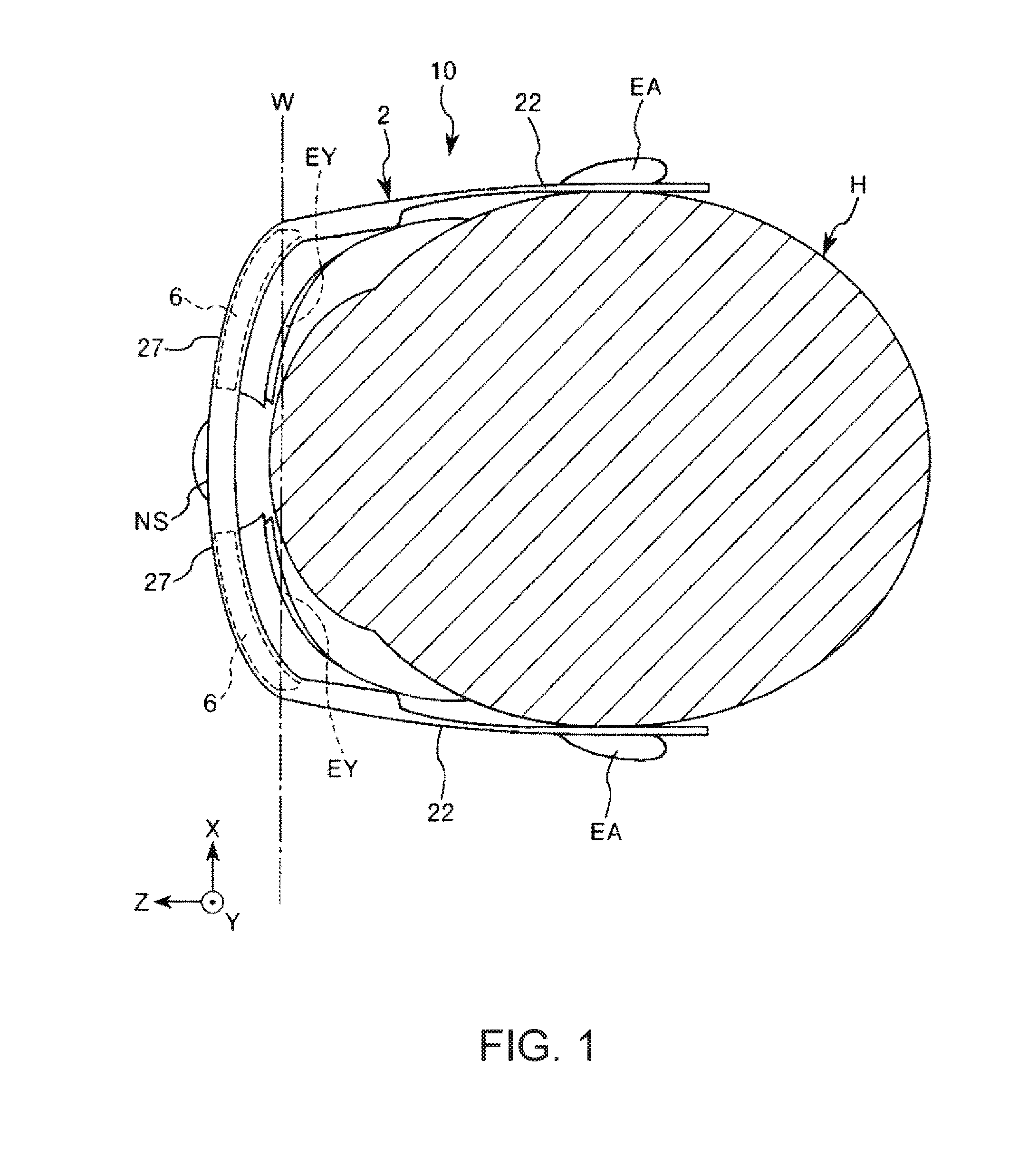
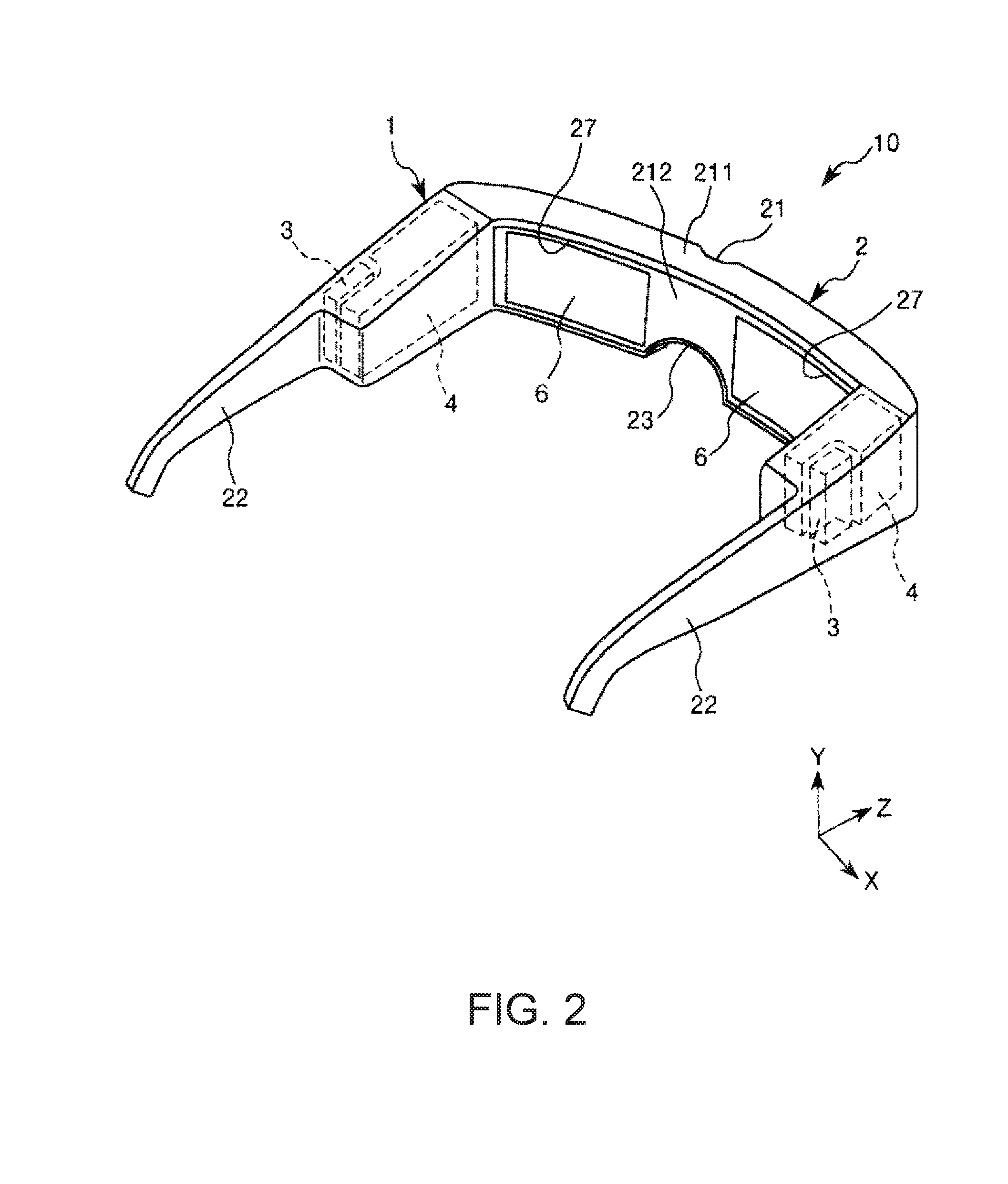
[0042]FIG. 1 shows a schematic configuration of a head mounted display including the image display apparatus according to the first embodiment of the invention. FIG. 2 is a schematic perspective view of the head mounted display shown in FIG. 1. FIG. 3 diagrammatically shows the configuration of the image display apparatus shown in FIG. 1. FIG. 4 diagrammatically shows the configuration of an image generator shown in FIG. 2. FIGS. 5A and 5B show an example of drive signals from a drive signal generator shown in FIG. 4. FIG. 6 is a plan view of a light sweeper shown in FIG. 4. FIG. 7 is a cross-sectional view of the light sweeper shown in FIG. 6 (cross-sectional view taken along X1 axis). FIGS. 8A to 8D show a schematic configuration of an optical element shown in FIG. 3, in which FIG. 8A is a front view, FIG. 8B is a plan view, FIG. 8C is a right side view, and FIG. 8D is a left ...
second embodiment
[0242]An image display apparatus according to a second embodiment of the invention will next be described.
[0243]FIGS. 12A and 12B diagrammatically show the configuration of the image display apparatus according to the second embodiment of the invention.
[0244]The second embodiment will be described below. In the following description, items different from those in the first embodiment described above will be primarily described and the same items as those in the first embodiment will not be described. Further, in FIGS. 12A and 12B, the same items as those in the embodiment described above have the same reference characters.
[0245]An image display apparatus 1 according to the second embodiment only differs from the image display apparatus 1 according to the first embodiment in terms of the configuration of each of the first hologram element 351 and the second hologram element 651.
[0246]That is, each of the first hologram element 351 and the second hologram element 651 according to the ...
third embodiment
[0253]An image display apparatus according to a third embodiment of the invention will next be described.
[0254]FIG. 13 diagrammatically shows a schematic configuration of a head-up display including the image display apparatus according to the third embodiment of the invention.
[0255]The third embodiment will be described below. In the following description, items different from those in the first and second embodiments described above will be primarily described and the same items as those in the first and second embodiment will not be described. Further, in FIG. 13, the same items as those in the embodiments described above have the same reference characters.
[0256]An image display apparatus 1 according to the third embodiment only differs from the image display apparatus 1 according to the first and second embodiments in that it is part of a head-up display 10′ attached to a ceiling of a car for use.
[0257]That is, the image display apparatus 1 according to the third embodiment is a...
PUM
 Abstract
Description
Claims
Application Information