Device and method for modelling a cornea

a technology of a device and a model is applied in the field of devices and a model of a cornea, which can solve the problems of difficult prediction of cut results, no known solution, and difficult planning of cuts

Active Publication Date: 2016-06-09
OPTIMO MEDICAL
View PDF10 Cites 4 Cited by
  • Summary
  • Abstract
  • Description
  • Claims
  • Application Information

AI Technical Summary

Benefits of technology

[0039]In addition to the computerized device for modeling a cornea, the present invention moreover relates to a computer-implemented method for modeling a cornea for simulating tissue cuts in the cornea and to a computer program product comprising a non-transient computer-readable medium with computer program code stored thereon, which computer program code is configured to control a processor in such a way that the processor executes the method for modeling the cornea. The computer-implemented method comprises the execution of the following steps by the processor: loading patient-specific corneal data, generating a patient-specific finite element model of the cornea; distributing a first group of tissue fibers, with main fibers t...

Problems solved by technology

Although tissue cuts can be carried out very precisely by means of laser pulses—much more accurately compared to e.g. manually using a scalpel—the change in the tissue form emerging in the case of tissue cuts as a result of th...

Method used


Image

  • Device and method for modelling a cornea
  • Device and method for modelling a cornea
  • Device and method for modelling a cornea

Examples


Embodiment Construction

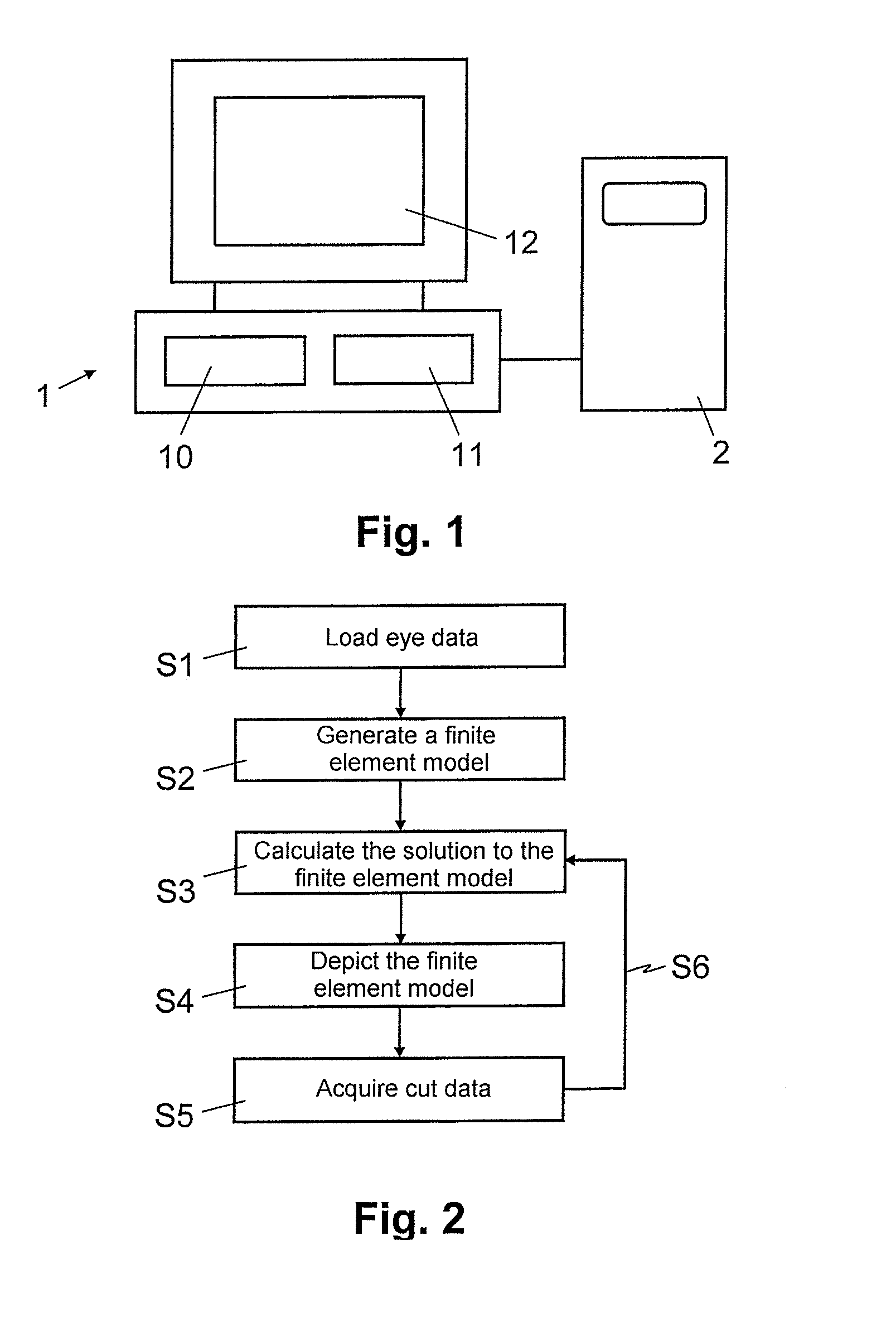
[0049]In FIG. 1, reference sign 1 relates to a computerized device for modeling a cornea for simulating tissue cuts in the cornea. The device 1 comprises an operational computer with at least one processor 10 and storage 11, connected to the processor 10, for storing data (data storage) and computer program code (program storage). In the embodiment in accordance with FIG. 1, the device 1 moreover comprises a display 12, e.g. an LED or LCD monitor. As depicted schematically in FIG. 1, the device 1 is connected in a variant to a computerized data source 2 external to the device 1, for example by way of a wired or wireless communication interface. The data source 2 comprises one or more processors and it is configured to transmit eye data, including patient-specific corneal data and / or population-based sclera data, to the device 1, as will be described in more detail below. Depending on the embodiment variant, the data source 2 comprises an ophthalmological measuring device for acquiri...


PUM


Abstract

A patient-specific finite element model of the cornea is generated for the purposes of modeling a cornea for simulating tissue cuts in the cornea. A first group of tissue fibers, with main fibers that extend parallel to the surface of the cornea, is distributed in the finite element model in accordance with a first distribution function. Moreover, a second group of tissue fibers, with inclined cross-linked fibers that do not extend parallel to the surface of the cornea, is distributed in the finite element model in accordance with a second distribution function. Here, the second distribution function distributes the cross-linked fibers with a non-uniform weighting function over the depth of the cornea, from the outer surface of the cornea to the inner surface of the cornea.

Description

CROSS REFERENCE TO RELATED APPLICATIONS[0001]This application is a 371 National State application of International Application No. PCT / EP2014 / 001791 filed on Jun. 30, 2014, which claims priority of European Serial Number 13003481.2 filed on Jul. 10, 2013, both of which are incorporated herein by reference in their entireties.BACKGROUND OF THE INVENTION[0002]1. Field of the Invention[0003]The present invention relates to a device and a method for modeling a cornea. In particular, the present invention relates to a computerized device and a computer-implemented method for modeling a cornea for simulating tissue cuts in the cornea, wherein the computerized device comprises a processor programmed to generate a patient-specific finite element model of the cornea.[0004]2. Description of the Prior Art[0005]A plurality of refractive errors such as myopia (shortsightedness), hyperopia (farsightedness) or astigmatism are corrected these days by means of surgical interventions on the eye. Here...

Claims


Application Information

Patent Timeline
IPC IPC(8): G06F19/12G06F17/50G06F30/00G16Z99/00
CPCG06F17/5009G06F19/12A61F9/013A61F9/00825A61F2009/00853A61F2009/00897A61B34/10A61B2034/105G16H50/50G16B5/00G16Z99/00G06F30/00G06F30/20
Inventor STUDER, HARALD P.RIEDWYL, HANSJORGBUCHLER, PHILIPPEROBERTS, CYNTHIA J.
Owner OPTIMO MEDICAL
Why Eureka
Try Eureka