Apparatus and Method for DEF Tank Filling

a technology of def tank and apparatus, which is applied in the direction of machines/engines, transportation and packaging, liquid transfer devices, etc., can solve the problems of diesel exhaust high levels of nitric oxide and nitrogen dioxide into the atmosphere, diesel engine high levels of nitric oxide and nitrogen dioxide need to be lowered even further, etc., to achieve the effect of convenient us

Inactive Publication Date: 2016-06-16
OROURKE SEAN J
View PDF2 Cites 6 Cited by
  • Summary
  • Abstract
  • Description
  • Claims
  • Application Information

AI Technical Summary

Benefits of technology

[0027]Particularly preferred in all modes of the device, the second hose is engaged to provide a sealed pathway for air to escape from the DEF tank during refill. This decreases the time required for the tank to fill by removing back pressure to the first hose connection. Further, by engaging the first hose to fill and engaging the second hose in a sealed relation to the DEF tank to vent, spillage is eliminated or significantly decreased.
[0028]In a second mode of the device, the configuration of hoses remains substantially the same. However, the operation is enhanced using a biased one-way valve positioned adjacent the dispensing end of the first hose and in the second hose adjacent to the engagement of the second hose to the venting aperture of the DEF tank. The one-way valve in the first hose provides a means to prevent back flow of the DEF fluid from the nozzle end to the tank.
[0029]Additionally the location of the biased or spring-loaded one way valves adjacent both the dispensing end of the first hose and the of the second hose adjacent the engagement to the venting aperture, prevents the communication of ambient air, to the interior of both hoses, and the interior of the container housing the refill supply of DEF. Such is most important to prevent the forming of crystals in the hoses and the reservoir of DEF which occurs should ambient air communicated with the fluid sufficient to evaporate the water therefrom.
[0031]Such sensing to automatically cease fluid dispensing is desirable to render the device to automatically shut off to avoid any problems with fluid being pumped into the DEF tank which might cause a rupture. Further, automatic cessation of fluid dispensing renders the device usable by the general public driver who may not have the skills to ascertain when the DEF tank is full.
[0034]It is one principal object of this invention to provide an easy to use DEF fluid refill system.
[0035]It is an additional object of this invention to provide such system which is usable by professionals and drivers alike and provides a means to prevent air flow to the DEF filling hoses and fluid reservoir and in some modes automatic shut off.

Problems solved by technology

Unfortunately in years past, diesel engines have had a problem with the exhaust emitted by the engine after the pressure-induced combustion.
In addition to particulate matter exhausted, such engines also exhaust high levels of nitric oxide and nitrogen dioxide into the atmosphere.
However, even with these efforts the high levels of nitric oxide and nitrogen dioxide in diesel exhaust needed to be lowered even further.
This results in an exhaust from the vehicle or engine in which the NOx emissions are rendered harmless.
However, due to the recent addition of such DEF tanks to vehicles, a problem has arisen for both motorists and vehicle service establishments.
However, containers for such refills, usable by motorists and service establishments alike have not addressed this two-hose requirement well.
Additionally, even when addressed with two hoses, the current hoses used for filling DEF tanks, make no provision to prevent air from reaching the reservoir of DEF fluid in the hose, the refill container or the tank.
Further, such crystals, in some cases, will dissolve during filling of the DEF tank into the fluid.
Such is not desirable as increased urea by volume in the fluid injected to the exhaust system can change the reaction during such injection.
Still, further available refill containers and refill tanks are cumbersome and slow.
Various limitations of the related art will become apparent to those skilled in the art upon a reading and understanding of the specification below and the accompanying drawings.

Method used


Image

  • Apparatus and Method for DEF Tank Filling
  • Apparatus and Method for DEF Tank Filling
  • Apparatus and Method for DEF Tank Filling

Examples


Embodiment Construction

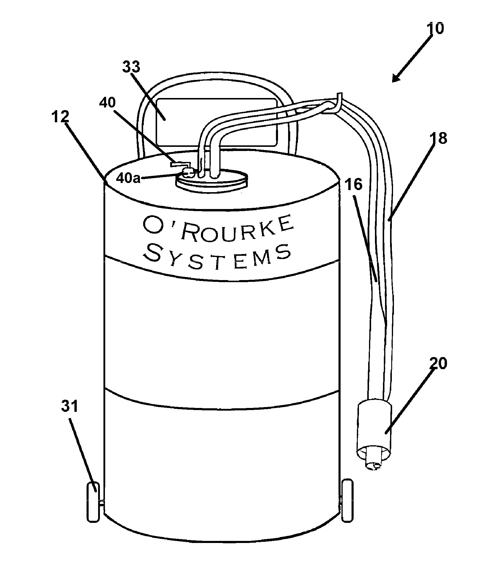
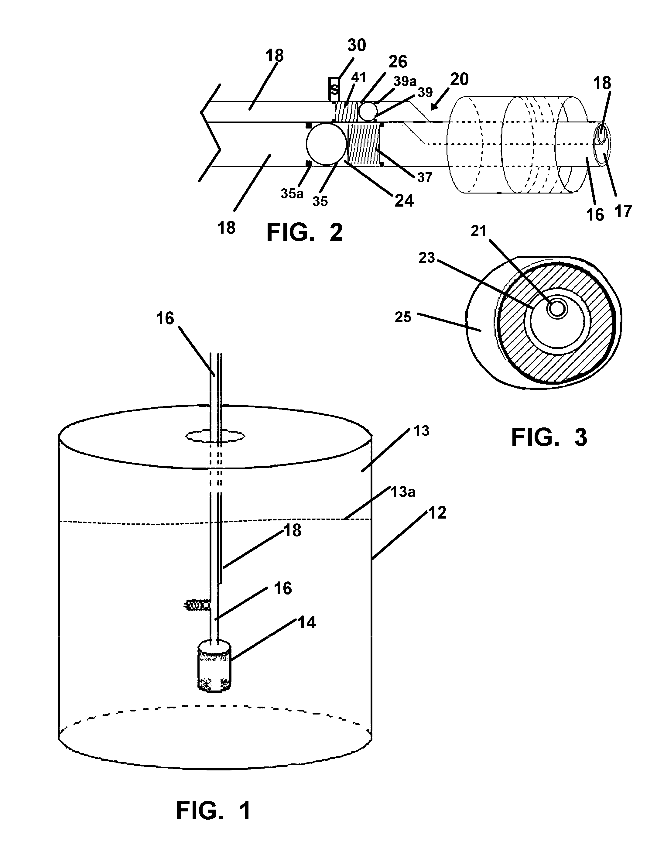
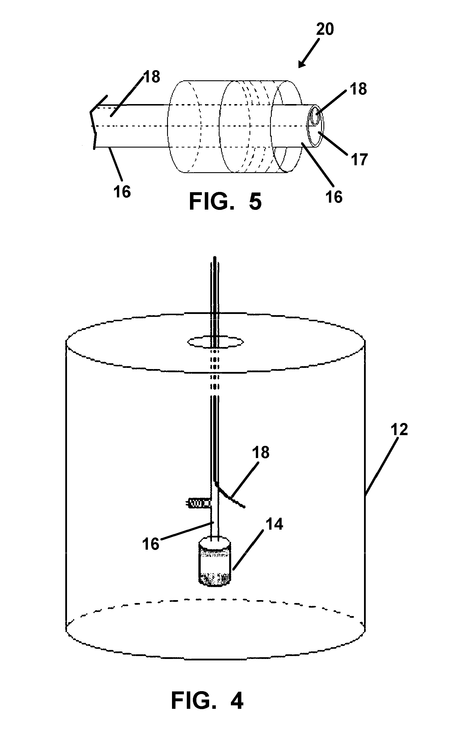
[0044]Referring now to the drawings of FIGS. 1-7 depicting the various modes of the refill device 10, which is shown configured in an as-used position in FIG. 7.

[0045]Shown in FIG. 1, the device 10 in all modes includes a DEF fluid refill reservoir 12 having an interior cavity 13 which is filled with a supply of DEF fluid 13a therein. A mechanical or the shown electric pump 14 is placed in operative communication with the DEF fluid 13a, and pumps a pressurized fluid supply to the first end of an operatively engaged first tube 16 or conduit, which is employed for refilling a DEF tank on a diesel vehicle.

[0046]Also depicted in FIG. 1 and other figures herein, is a second tube 18 or conduit which is configured to be employed for venting the vehicle engaged DEF tank of both air and overflowing DEF fluid during a refill thereof. In all modes, the device 10 is configured for engagement to a fluid reservoir 12 with the first end of the first tube 16 submerged in fluid 13a and engaged with ...


PUM


Abstract

A refill device for a diesel exhaust fluid tank is provided which employs a nozzle connection to the fluid tank to provide replenishment of the exhaust fluid from a reservoir. Fluid from the reservoir is communicated to the fluid tank using a pump providing a pressurized fluid supply through a first hose. A second hose engaged with the nozzle vents air from the fluid tank for the duration of filling by the first hose.

Description

BACKGROUND OF THE INVENTION[0001]1. Field of the Invention[0002]This application claims priority to U.S. Provisional Patent Application Ser. No. 62 / 090,263 filed on Dec. 10, 2014.[0003]The present invention relates to fueling of diesel vehicles. More particularly, it relates to a device and method employed for refilling the Diesel Exhaust Fluid (DEF) tank which has become a required component of modern emission-controlled diesel engines to meet emission standards.[0004]2. Prior Art[0005]Diesel engines have been a very efficient power provider for vehicles since the dawn of the automobile. Such engines are extremely efficient when compared to gasoline engines and have for decades provided excellent reliability.[0006]The high mileage of diesel engines has to do primarily with the fuel itself, and with the design and function of such engines. Diesel fuel has in each gallon of fuel, more energy than gasoline. Thus, the employment of diesel fuel in an internal combustion engine, yields m...

Claims


Application Information

Patent Timeline
Patent Type & Authority Applications(United States)
IPC IPC(8): B67D7/02B67D7/58B67D7/38F01N3/20
CPCB67D7/0294B67D7/38B67D7/58F01N3/2066B67D7/02B67D7/3227B67D7/362B67D7/68F01N2610/1413
Inventor O'ROURKE, SEAN J.
Owner OROURKE SEAN J
Why Eureka
Try Eureka