Sealing Device, Rotating Machine, and Method for Manufacturing Sealing Device

Inactive Publication Date: 2016-06-16
MITSUBISHI HITACHIPOWER SYST LTD
View PDF10 Cites 4 Cited by
  • Summary
  • Abstract
  • Description
  • Claims
  • Application Information

AI Technical Summary

Benefits of technology

[0015]The aspect of the present invention can avoid the blow-by of the working fluid without increasing the risk of sticking between the adjacent seal segments. This benefit can reduce unnecessa

Problems solved by technology

The fitting portion provided by the arrangements, however, produces a likelihood that the adjacent segments will stick to each other.
The sticking occurs when the clearance between the protrusion and the recess formed in the abutting surfaces is excessively narrow or when impurities, such as scale originating in an upstream mech

Method used


Image

  • Sealing Device, Rotating Machine, and Method for Manufacturing Sealing Device
  • Sealing Device, Rotating Machine, and Method for Manufacturing Sealing Device
  • Sealing Device, Rotating Machine, and Method for Manufacturing Sealing Device

Examples


first embodiment

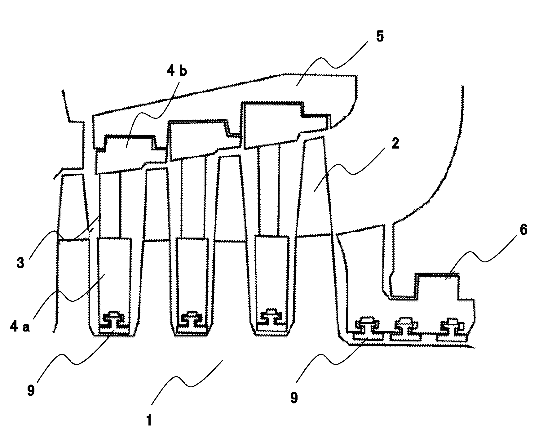
[0031]FIG. 1 is a schematic diagram of stages of a steam turbine that includes a sealing device, a rotating machine, and a method for manufacturing a sealing device according to a first embodiment of the present invention.

[0032]As illustrated in FIG. 1, each stages of a steam turbine include a combination of a moving blade 2 connected to a rotor 1, and a stationary blade 3 disposed between a diaphragm outer race 4b and a diaphragm inner race 4a. The steam turbine includes the stages in an axial direction of the rotor 1 and thus structures turbine stages. The turbine stages, enclosed in a single or multiple casing, achieve the air tightness of the turbine. In the first embodiment, the steam turbine includes an inner casing 5 and an outer casing (not shown).

[0033]In order to rotate the rotor 1 efficiently using steam that flows through the inside of the inner casing 5, the steam turbine configured as described above is required to improve sealing performance between the rotor 1 and th...

second embodiment

[0054]The following describes, with reference to the relevant accompanying drawing, a sealing device, a rotating machine, and a method for manufacturing a sealing device according to a second embodiment of the present invention.

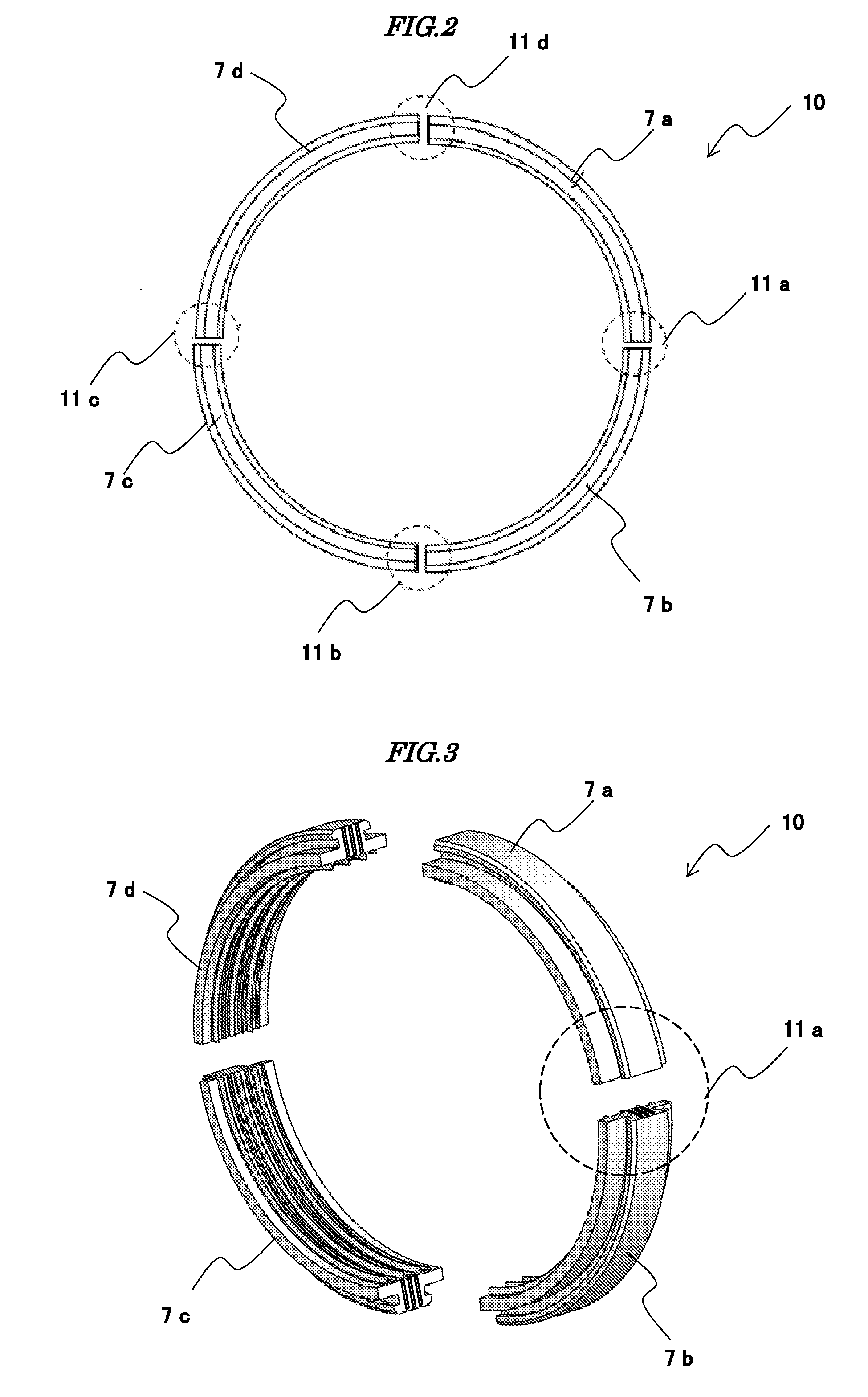
[0055]FIG. 11 is a schematic view illustrating a relation between an exemplary sectional shape and adjacent seal segments that face each other, the view, taken along the plane V-V in FIG. 4, regarding a sealing device, a rotating machine, and a method for manufacturing a sealing device according to a second embodiment of the present invention, the sealing device seen in the direction perpendicular to the cutting plane. In FIG. 11, like parts are identified by the same reference numerals as in FIGS. 1 to 10 and descriptions therefor will be omitted.

[0056]FIG. 11 particularly shows a situation in which a joint surface 8 of a seal segment having a section 21a is spaced apart from a joint surface 8 of a seal segment having a section 21b to thereby produce a clear...


PUM


Abstract

It is an object of the present invention to provide a sealing mechanism that, while preventing a clearance that passes in an axial direction through an entire abutting surface without involving large resistance and that invites blow-by of a working fluid, can prevent adjacent seal segments from sticking to each other, and a method for manufacturing the sealing mechanism. A sealing device includes: an annular sealing ring that includes a plurality of seal segments annularly juxtaposed; a plurality of seal fins provided in an axial direction on an inner peripheral surface of the sealing ring; a joint surface on a circumferential end of the seal segment, the joint surface facing a joint surface on an adjacent seal segment; a groove that extends in a radial direction in the joint surface; and a protrusion formed by bending part of a surface that constitutes a long side of the groove toward an outside of the joint surface.

Description

BACKGROUND OF THE INVENTION[0001]1. Field of the Invention[0002]The present invention relates to a sealing device, a rotating machine, and a method for manufacturing a sealing device.[0003]2. Description of Related Art[0004]A large rotating machine, such as a steam turbine or a gas turbine, generally has a casing surrounding a rotor disposed inside the rotating machine so as to enclose the rotor and to thus hermetically seal a working fluid. The casing, when manufactured, typically includes an upper half and a lower half that are brought together into one assembly to sandwich the rotor. The flange faces of the upper half and the lower half partly protrude. Bolts, passing through and tightening the flange faces, ensure the air tightness of the casings.[0005]Such a rotating machine has a clearance between the rotor and a stator. The working fluid that may leak from the clearance could lead to energy loss, and for this reason, the rotating machine typically includes a sealing mechanism...

Claims


Application Information

Patent Timeline
IPC IPC(8): F01D11/02F16J15/447
CPCF01D11/02F05D2220/32F05D2240/55F16J15/447F16J15/442
Inventor MIZUMI, SHUNSUKEKUDO, TAKESHIOGATA, KOJIOIKAWA, SHINJI
Owner MITSUBISHI HITACHIPOWER SYST LTD
Why Eureka
Try Eureka