Torsional vibration reducing device

a torsional vibration and reducing device technology, applied in the direction of vibration suppression adjustment, rotating vibration suppression, shock absorbers, etc., can solve the problems of possible deterioration of damping performance, reduce sliding friction, and reduce the effect of sliding friction

Active Publication Date: 2016-06-16
TOYOTA JIDOSHA KK
View PDF4 Cites 13 Cited by
  • Summary
  • Abstract
  • Description
  • Claims
  • Application Information

AI Technical Summary

Benefits of technology

[0008]This invention provides a torsional vibration reducing device which reduces sliding friction between a rolling body and a connection member that connects rolling bodies with each other.
[0014]In accordance with the present invention, the two contact portions of the connection member come into point contact or line contact with the outer peripheral surface of the rolling body. Therefore, a contact area between the rolling body and the connection member can be reduced as compared to a case in which the connection member is disposed along a side surface of the rolling body, and the rolling body and the connection member are in surface contact with each other. Accordingly, it is possible to reduce sliding friction between the rolling body and the connection member when the rolling body reciprocates with the fluctuations in the transmitted torque. It is also possible to suppress a situation in which the sliding friction produces resistance to hinder the reciprocation of the rolling body. As a result, damping performance can be improved. Also, since the accommodating portion of the connection member holds the rolling body from the outer peripheral surface side, an increase in an axial length of the torsional vibration reducing device can be suppressed as compared to a case in which the connection member is disposed along the side surface of the rolling body. Moreover, it is not necessary to provide a configuration for connecting the rolling bodies in the rolling body, and a machining cost of the rolling body can be correspondingly reduced. The two contact portions come into point contact or line contact with the outer peripheral surface on the outer side with respect to the center of gravity of the rolling body in the radial direction of the rotating body and on the opposite sides with the center of gravity of the rolling body therebetween in the circumferential direction of the rotating body. Accordingly, it is possible to suppress escape of the rolling body from the connection member. Also, by disposing the connection members on the opposite sides of the rotating body, a load associated with contact between the outer peripheral surface of the rolling body and the connection members can be applied to the opposite end portions of the rolling body. As a result, the rolling body can be stably reciprocated along the rolling surface, so that the damping performance can be further improved.

Problems solved by technology

As a result, damping performance is possibly deteriorated.

Method used


Image

  • Torsional vibration reducing device
  • Torsional vibration reducing device
  • Torsional vibration reducing device

Examples


first embodiment

[0027](First Embodiment)

[0028]FIG. 3 is a sectional view illustrating a portion in one example of a torsional vibration reducing device according to a first embodiment. The torsional vibration reducing device includes a rotating body 1 that is attached to an object to be damped. The rotating body 1 is a disk-shaped member. Circumferentially-long guide holes 2 are formed at positions radially shifted from the center of rotation of the rotating body 1. The guide holes 2 are formed passing through the rotating body 1 in a plate thickness direction. The guide holes 2 are positioned at predetermined intervals in a circumferential direction of the rotating body 1. As one example, eight guide holes are provided. The guide holes 2 have a shape formed by curving an oval shape or an elliptical shape.

[0029]A rolling body 3 that reciprocates by an inertial force when torque transmitted to the rotating body 1 fluctuates is inserted into each of the guide holes 2. The rolling body 3 is pressed ag...

second embodiment

[0038](Second Embodiment)

[0039]FIG. 4 is a sectional view in the rotating body radial direction illustrating a portion in one example of a torsional vibration reducing device according to a second embodiment. The example shown therein is an example in which the connection members 5 are disposed on the inner side of the rolling body 3 in the radial direction of the rotating body 1 and on the opposite end portion sides of the rolling body 3 in the axial direction. In a configuration shown in FIG. 4, a load associated with contact between the outer peripheral surface 3a of the rolling body 3 and the connection members 5 is applied to the opposite end portions of the rolling body 3 in the axial direction. Therefore, the rolling body 3 can be more stably reciprocated than the example shown in FIG. 3, so that the damping performance is further improved.

third embodiment

[0040](Third Embodiment)

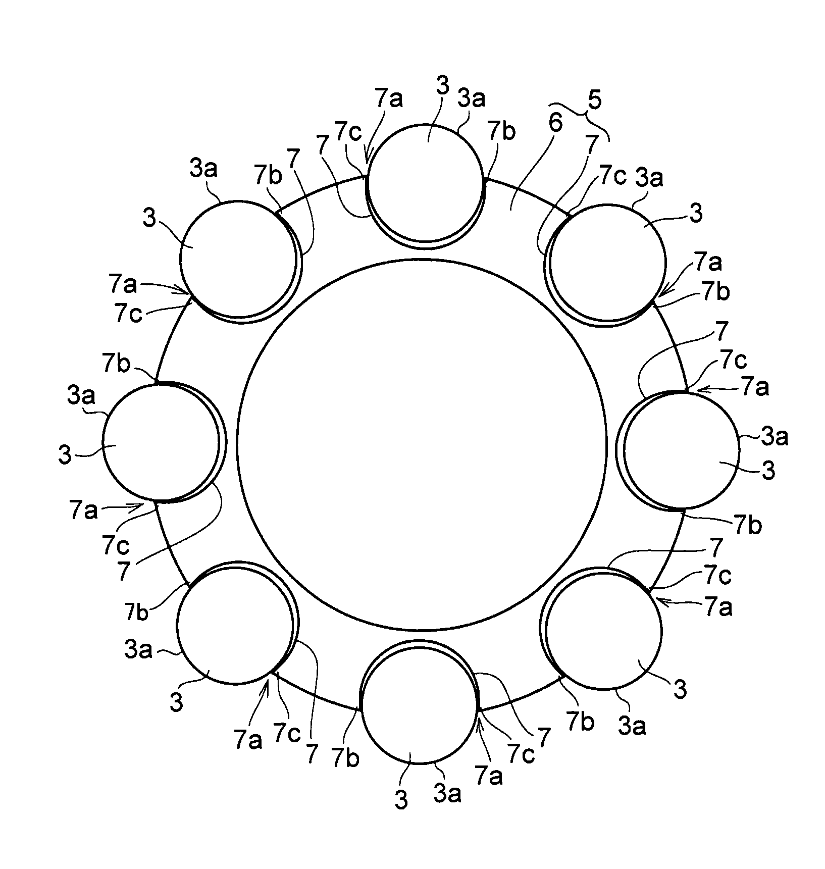
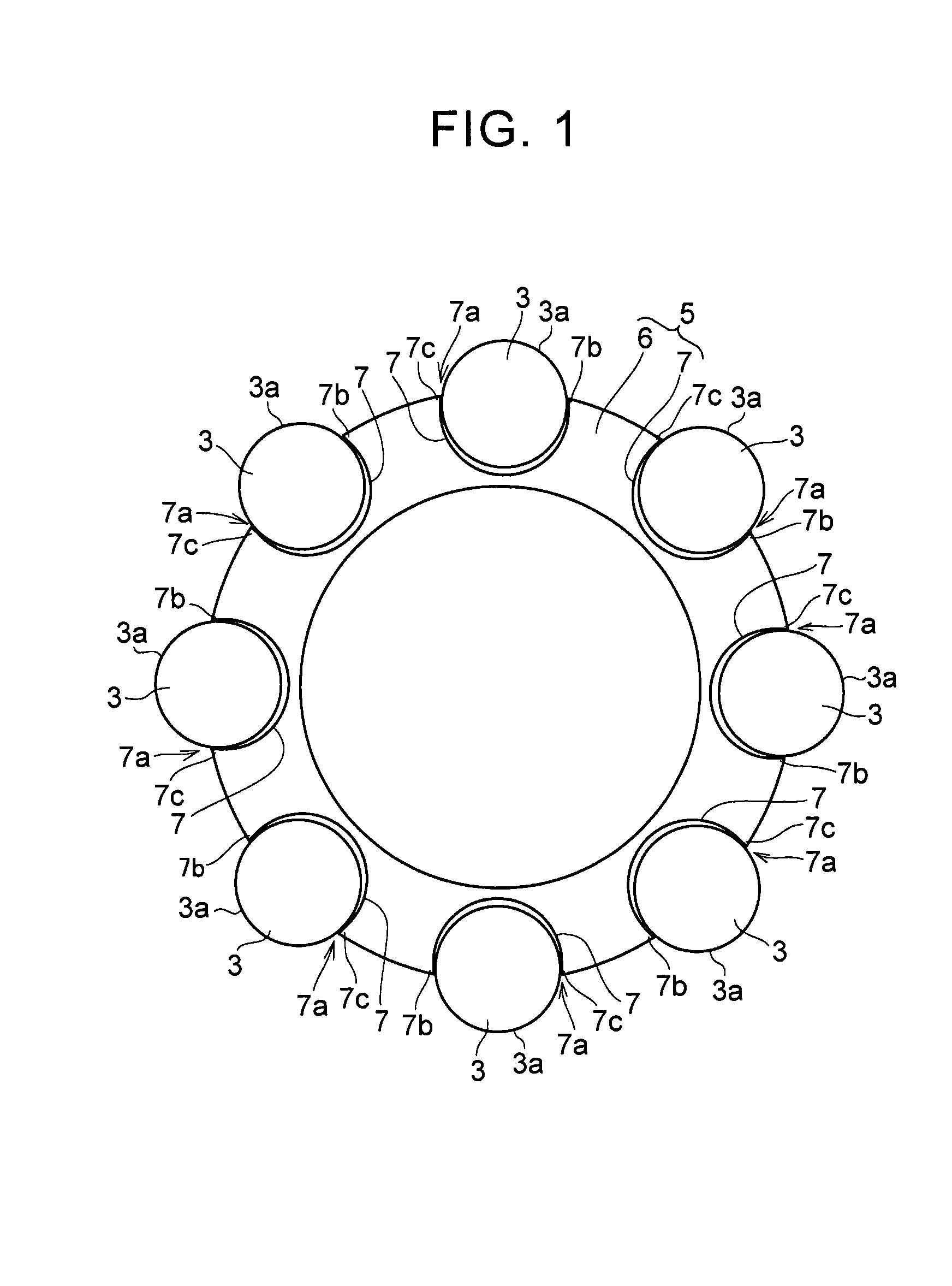
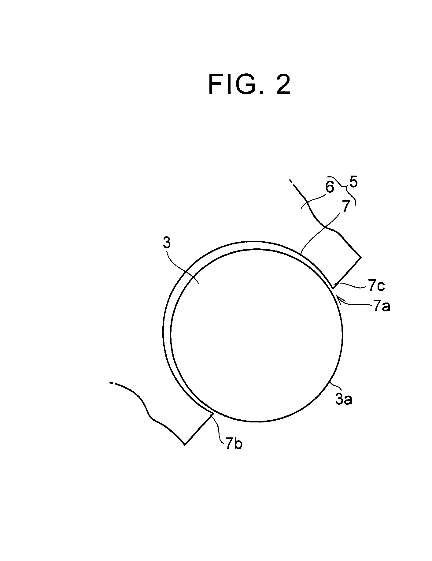
[0041]FIG. 5 is a view illustrating one example of a connection member according to a third embodiment. In the example shown in FIG. 5, the three guide holes 2 are formed at predetermined intervals in the circumferential direction of the rotating body 1. The support portion 6 in the connection member 5 has a Y shape. The support portion 6 is formed such that free end portions are positioned corresponding to the guide holes 2, respectively. The accommodating portions 7 having the opening portions 7a that open outward in the radial direction of the rotating body 1 are provided at the free end portions, respectively.


PUM


Abstract

A torsional vibration reducing device is provided. The torsional vibration reducing device includes a rotating body, a plurality of rolling bodies, and a connection member. The connection member connects the plurality of rolling bodies, and at least two contact portions are positioned on an inner surface of each of the plurality of accommodating portions, a portion of an outer peripheral surface of each of the plurality of rolling bodies being positioned in each of the plurality of accommodating portions, and the outer peripheral surface of each of the plurality of rolling bodies being configured to come into point contact with the contact portions in the circumferential direction of the rotating body.

Description

INCORPORATION BY REFERENCE[0001]The disclosure of Japanese Patent Application No. 2014-253727 filed on Dec. 16, 2014 including the specification, drawings and abstract is incorporated herein by reference in its entirety.BACKGROUND OF THE INVENTION[0002]1. Field of the Invention[0003]The invention relates to a device that reduces torsional vibration by reciprocation of a rolling body.[0004]2. Description of Related Art[0005]One example of this type of device is described in Japanese Patent Application Publication No. 2014-47805. The device includes a plate member that is attached to a crankshaft of an engine. A recessed accommodating portion that is formed in an annular shape is formed in the plate member. A plurality of mass bodies that reciprocate by fluctuations in transmitted torque are disposed in the accommodating portion. The mass bodies are connected by connection members that are disposed along opposite side surfaces of the mass bodies.[0006]Also, Japanese Patent Application...

Claims


Application Information

Patent Timeline
Patent Type & Authority Applications(United States)
IPC IPC(8): F16F15/14
CPCF16F15/145
Inventor MIYAHARA, YUAMANO, HIROYUKISUZUKI, YUJITSUKANO, HUSAHIROMATSUMOTO, MORIHIROHONDA, ATSUSHI
Owner TOYOTA JIDOSHA KK
Why Eureka
Try Eureka