Eureka AIR delivers breakthrough ideas for toughest innovation challenges, trusted by R&D personnel around the world.

Inspection system for inspecting an object and inspection method for same

a three-dimensional inspection system and object technology, applied in the field of object inspection, can solve the problems of misinterpretation between what is displayed on the screen or printout and the corresponding regions of the inspected object, faulty identification of the targeted region of the object, and the known system suffers from several drawbacks, so as to avoid combining errors, simplify the computation of images, and be more cost-effective

Active Publication Date: 2016-06-16
POLYRIX
View PDF13 Cites 89 Cited by
  • Summary
  • Abstract
  • Description
  • Claims
  • Application Information

AI Technical Summary

Benefits of technology

The invention uses projectors to display inspection information directly onto an object, instead of relying on a computer screen. This eliminates the need for calibration between the device used for acquiring the shape of the object and the device used for projecting the inspection information. It simplifies the user experience and reduces costs by avoiding errors from combining two devices. The invention also simplifies the computation of the images needed to project the inspection information.

Problems solved by technology

Known systems however tend to suffer from several drawbacks.
In particular, the visualisation of the inspected object and inspection information on a display screen or a printout copy with specific viewpoints can lead to misconceptions between what is displayed on the screen or printout and the corresponding regions of the inspected object.
For example, and without being limitative, in a case where a specific region of the inspected object is targeted as needing to be reworked, an erroneous interpretation of the relationship between the displayed information and the physical object which is inspected can lead to faulty identification of the targeted region of the object.
Such misconceptions are especially likely to occur in cases where the object is symmetrical and can lead to the original defect remaining uncorrected and still be present on the final object.
Such misconceptions can be costly, time consuming and potentially dangerous if the region that was not properly reworked is critical.
Once again, however, known systems tend to suffer from several drawbacks.
However, the video-projector of the device disclosed in the application is not configured to capture object data relative to the specific shape of the outer surface of the object being inspected or assembled.
Consequently, the system disclosed in this application cannot be used to generate inspection information based on the acquired object data, such as portions of the outer surface of the object that are faulty or non-conforming with a reference, which is often valuable for operators in the inspection process.
Moreover, such a system is not cost efficient as it duplicates the components included in the system.
In addition, the laser projection device of known devices cannot project color information, can flicker due to the fact that the laser must sweep all the lines of the projected information, displays speckle and are not eye-safe.

Method used


Image

  • Inspection system for inspecting an object and inspection method for same
  • Inspection system for inspecting an object and inspection method for same
  • Inspection system for inspecting an object and inspection method for same

Examples


Embodiment Construction

[0032]In the following description, the same numerical references refer to similar elements. The embodiments, geometrical configurations, materials mentioned and / or dimensions shown in the figures or described in the present description are preferred embodiments only, given solely for exemplification purposes.

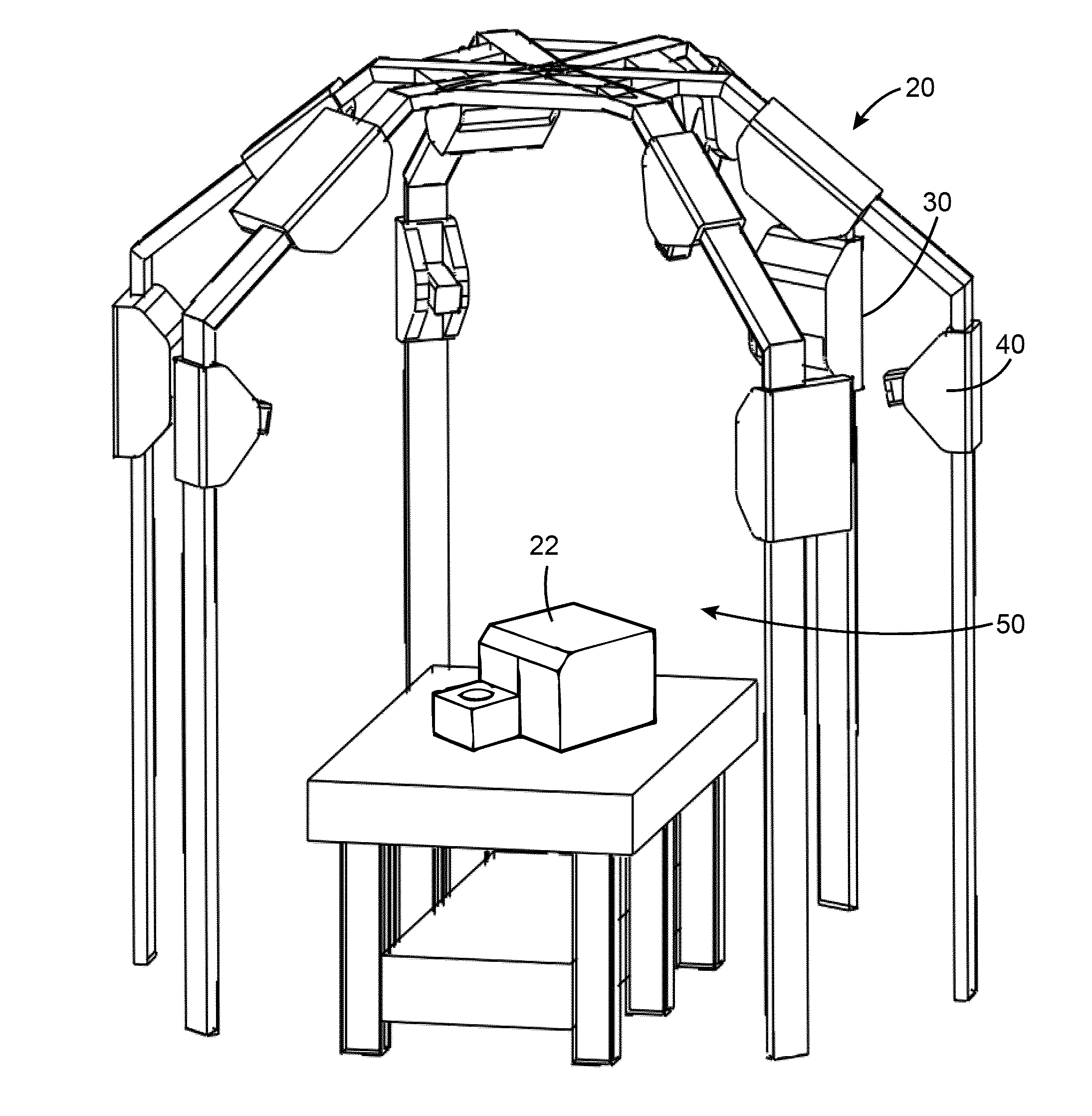
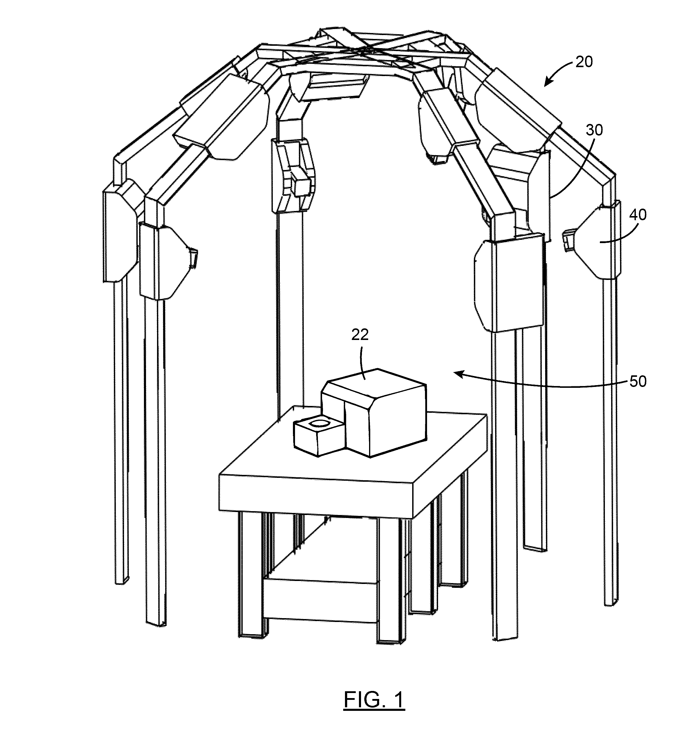
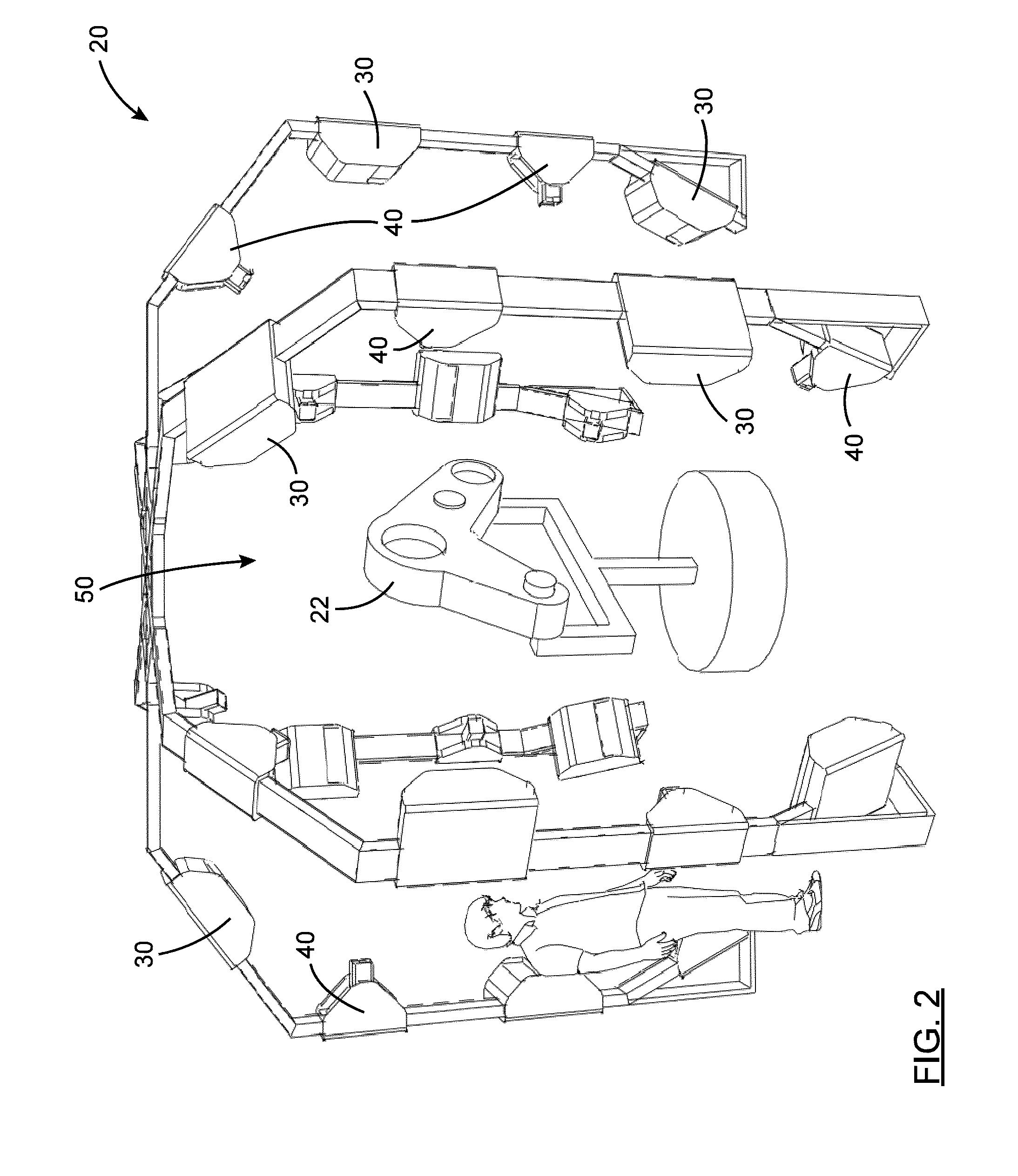
[0033]Moreover, although the embodiments of the three dimensional inspection system and corresponding parts thereof consist of certain geometrical configurations as explained and illustrated herein, not all of these components and geometries are essential and thus should not be taken in their restrictive sense. It is to be understood, as also apparent to a person skilled in the art, that other suitable components and cooperation thereinbetween, as well as other suitable geometrical configurations, can be used for the three dimensional inspection system, as will be briefly explained herein and as can be easily inferred herefrom by a person skilled in the art. Moreover, it will b...


PUM


Abstract

A system for inspecting an object has at least one light projector and at least one camera jointly defining a field of view and a computer operatively connected thereto. The computer is configured to acquire object data representative of the outer surface of the object through projection of light thereon by the light projector and acquisition of return light by the camera. The object data relates surface points on the outer surface of the object to one or more source point of the light projector. The computer is further configured to generate inspection information data based on the acquired object data and project the inspection information data on at least some of the surface points of the outer surface of the object using the corresponding source points of the at least one light projector. A method inspects an outer surface of an object.

Description

FIELD OF THE INVENTION[0001]The present invention relates to the field of object inspection. More particularly, it relates to a three dimensional inspection system for inspecting an object and to an inspection method for same.BACKGROUND[0002]Quality control is a constant concern in the manufacturing industry. Therefore, numerous tools have been developed over time to assist operators in performing inspection of manufactured objects at different stages of the manufacturing process.[0003]For example, several systems and corresponding methods of operation are known in the art to perform computerized dimensional and visual inspection of an object. Such systems typically capture object data relative to the object for subsequent processing by the system and visualisation by a user. Typically, inspection data generated by processing of the captured object data is visualized either on a display screen of a computer, using a three dimensional visualisation software where the inspected object...

Claims


Application Information

Patent Timeline
Patent Type & Authority Applications(United States)
IPC IPC(8): G01B11/25G01B11/00
CPCG01B11/002G01B11/25G01B11/245G01N21/8806
Inventor DESCHENES, JEAN-DANIELLAMBERT, PHILIPPEMARTEL-BRISSON, NICOLASQUIRION, SEBASTIEN
Owner POLYRIX
Why Eureka
Eureka Blog
Learn More