
Biological detection calibration system and operating method thereof

a biological detection and calibration system technology, applied in the direction of optical elements, fluorescence/phosphorescence, instruments, etc., can solve the problems of increasing the difficulty of light source calibration, affecting the operation efficiency of the system, and affecting the accuracy of the calibration results, so as to achieve convenient operation

Active Publication Date: 2016-06-16
WISTRON CORP
View PDF4 Cites 0 Cited by
  • Summary
  • Abstract
  • Description
  • Claims
  • Application Information

AI Technical Summary

Benefits of technology

[0008]The invention provides a biological detection calibration system, wherein a light detector is integrated with a carrier for biochemical examination for directly measuring the intensity of the light source of the biological detection device on the carrier, and the intensity of the light source is compensated by a controller of the biological detection device. The light source of the biological detection device does not need to be taken out during a calibration process, and thus the calibration of the light source is greatly simplified.
[0014]Based on the above, although different biological detection devices may adopt light sources with different designs, the lights of the light sources of the biological detection devices are all emitted to the carrier for biochemical examination. Considering this characteristic, the light calibration device and the biological detection calibration system of the invention integrate the light detector with the carrier for directly measuring the intensity of the light source of the biological detection device on the carrier, so as to detect the light intensity that the biological sample receives during actual examination. Moreover, the controller compares the intensity information of the light detected by the light detector with the predetermined value to adjust the intensity of the light source. Therefore, the light calibration device, the biological detection calibration system, and the operating method of the invention can be used to calibrate the light source of the biological detection device without disassembling the light source, which is very convenient in operation.

Problems solved by technology

The problem of luminous decay may occur on the light source (whether mercury lamps or LEDs) after the light source is used for a long period of time.
When such a problem occurs, a light calibration device is needed to calibrate the light source.
Through adjusting the intensity of the light source, erroneous detection results due to insufficient fluorescence resulting from luminous decay are prevented.
Thus, a method for taking out the light sources and effectively measuring the intensity thereof may differ according to different biological detection devices, which relatively increases the difficulty in light source calibration.
Moreover, in order to perform light source calibration, it is usually required to purchase an expensive and heavy light source calibration device, disassemble the light source, and install the light source calibration device for calibration process.
Such a calibration process is complex and requires much work, and the equipment costs are high, which are unfavorable for the development of light-weighted portable biological detection devices.

Method used


Image

  • Biological detection calibration system and operating method thereof
  • Biological detection calibration system and operating method thereof
  • Biological detection calibration system and operating method thereof

Examples


Embodiment Construction

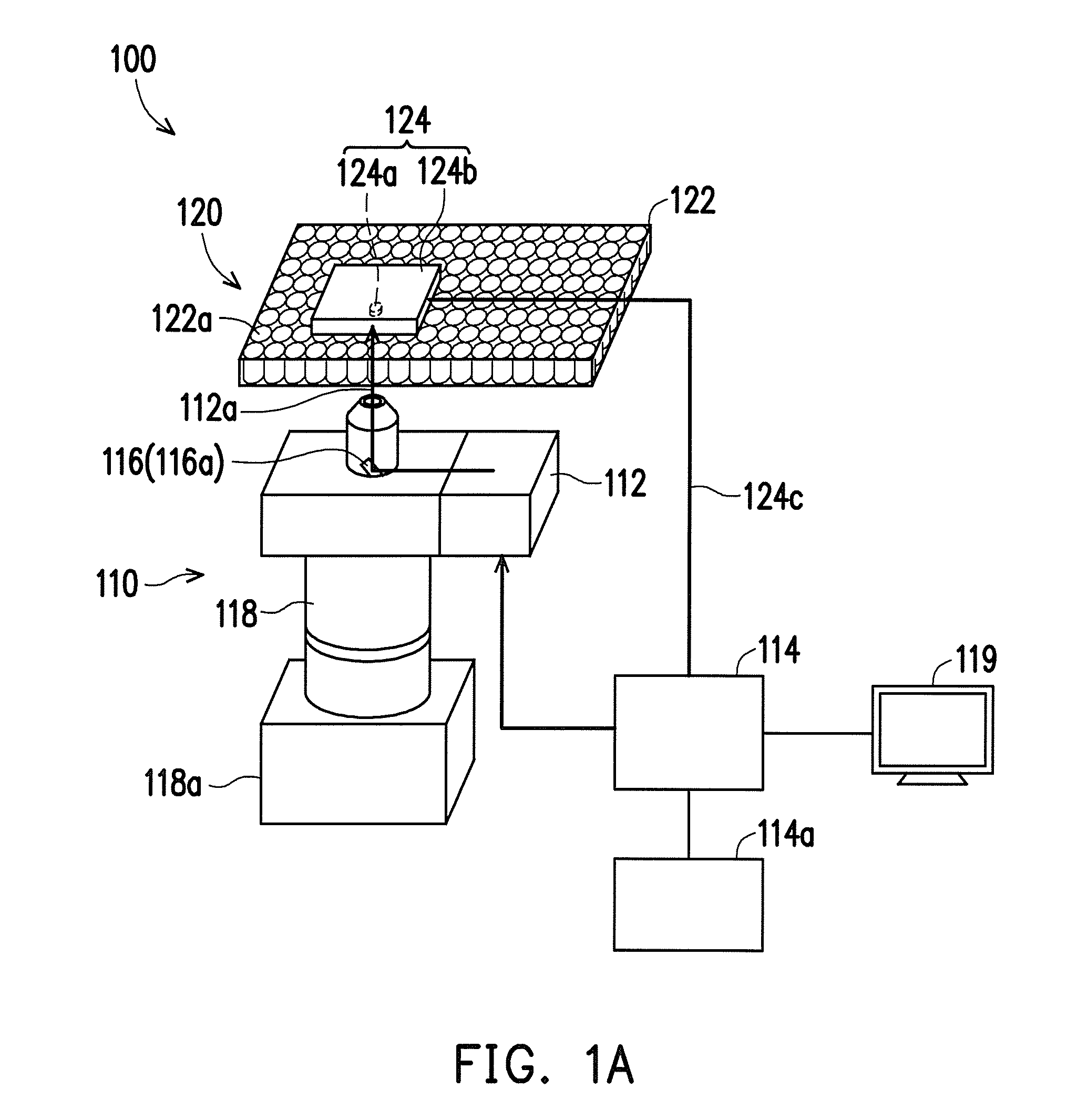
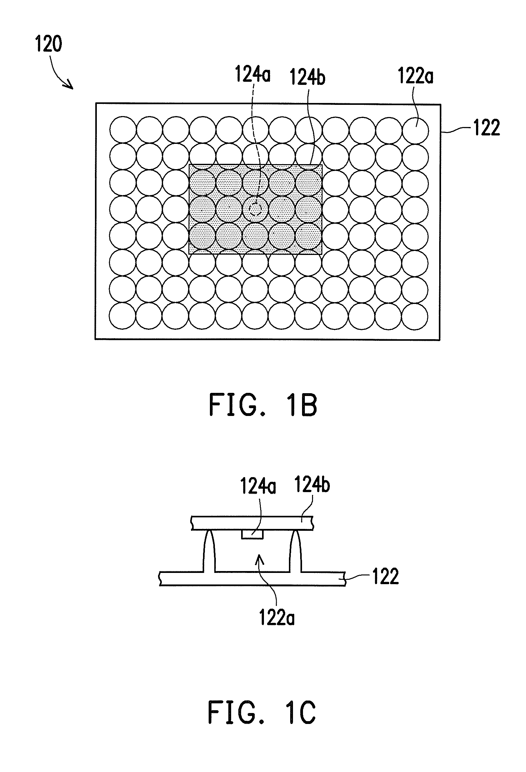
[0022]FIG. 1A is a schematic view of a biological detection calibration system according to an embodiment of the invention. FIG. 1B is a schematic top view of a light calibration device of the biological detection calibration system in FIG. 1A. FIG. 1C is a schematic cross-sectional view illustrating a part of the light calibration device of the biological detection calibration system in FIG. 1B.

[0023]Referring to FIG. 1A to FIG. 1C, a biological detection calibration system 100 of this embodiment includes a biological detection device 110 and a light calibration device 120. The biological detection device 110 includes a light source112 and a controller 114. In this embodiment, the biological detection device 110 is a fluorescence micrography detecting device, but it is noted that the biological detection device 110 is not limited thereto. The controller 114 is electrically connected to the light source 112 and applies a constant driving voltage, so as to control the light source 11...


PUM

PropertyMeasurementUnit
fluorescenceaaaaaaaaaa
fluorescence detectionaaaaaaaaaa
period of timeaaaaaaaaaa

Abstract

A biological detection calibration system includes a biological detection device and a light calibration device. The biological detection device is for detecting a biological sample and includes a light source and a controller electrically connected thereto to control the light source to emit a light. The light calibration device includes a carrier, disposed at a detecting position of the biological sample in the biological detection device to receive the light emitted from the light source, and a calibration sample, disposed on the carrier and including a light detector. The light detector is for detecting intensity of the light and transmitting intensity information to the controller. The controller reads the intensity information of the light and compares the intensity information with a predetermined value to modify driving energy of the light source so that the intensity of the light detected by the light detector is not less than the predetermined value.

Description

CROSS-REFERENCE TO RELATED APPLICATION[0001]This application is a divisional application of U.S. application Ser. No. 13 / 902,865, filed on May 27, 2013, now pending. The prior application Ser. No. 13 / 902,865 claims the priority benefit of Taiwan application serial no. 101129897, filed on Aug. 17, 2012. The entirety of each of the above-mentioned patent application is hereby incorporated by reference herein and made a part of this specification.BACKGROUND OF THE INVENTION[0002]1. Field of the Invention[0003]The invention relates to a light calibration device, a biological detection calibration system, and an operating method thereof, and particularly relates to a light calibration device, a biological detection calibration system, and an operating method thereof that are developed for a biological detection device emitting a light with certain intensity and wavelength to a biological sample to detect a fluorescence thereof.[0004]2. Description of Related Art[0005]Now, in the field of...

Claims


Application Information

Patent Timeline
Patent Type & Authority Applications(United States)
IPC IPC(8): G01N21/64G02B21/06G02B21/00G02B21/16
CPCG01N21/6458G02B21/16G01N21/6428G01N2201/127G02B21/0096G01N2201/062G02B21/06G01N21/274G01N21/6452G01D18/00G01N21/6486G01N2201/061G02B21/365
Inventor SHIH, WEN-HUI
Owner WISTRON CORP
Learn More