
High luminance solid state light source

a solid-state light source, high luminance technology, applied in the direction of semiconductor devices, lighting and heating apparatus, instruments, etc., can solve the problems of not being able to adapt to low-étendue applications, not being able to meet the requirements of not being able to provide suitable lasers at all required emission wavelengths. , to achieve the effect of high luminance, compact design and high efficiency

Inactive Publication Date: 2015-04-09
SIGNIFY HLDG BV +1
View PDF4 Cites 0 Cited by
  • Summary
  • Abstract
  • Description
  • Claims
  • Application Information

AI Technical Summary

Benefits of technology

The present invention provides a highly efficient and compact incoherent light source with improved collection efficiency. The use of a reflector and a rotatable support with a bearing at a distance from the rotational axis allows for a larger reflector without shadowing. The reflector collimates the collected radiation, and a cooling structure improves further cooling of the wavelength converting material. These technical effects lead to a more efficient and high luminance light source design.

Problems solved by technology

LEDs are still limited in their brightness and therefore can not be adapted to low Étendue applications.
However, suitable lasers are not available at all required emission wavelengths.
Especially in the green wavelength range there is a lack of direct laser diodes with appropriate performance and costs.
Furthermore, laser projection is still hampered by Speckle and other interference effects which require additional measures to ensure an acceptable picture quality.

Method used


Image

  • High luminance solid state light source
  • High luminance solid state light source

Examples


Embodiment Construction

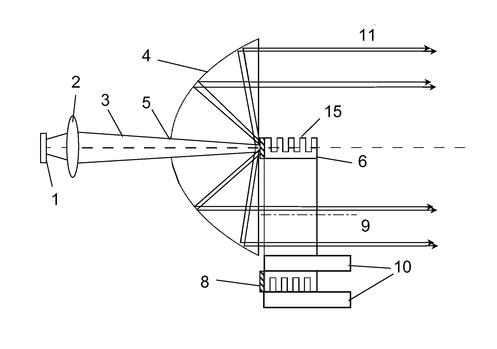
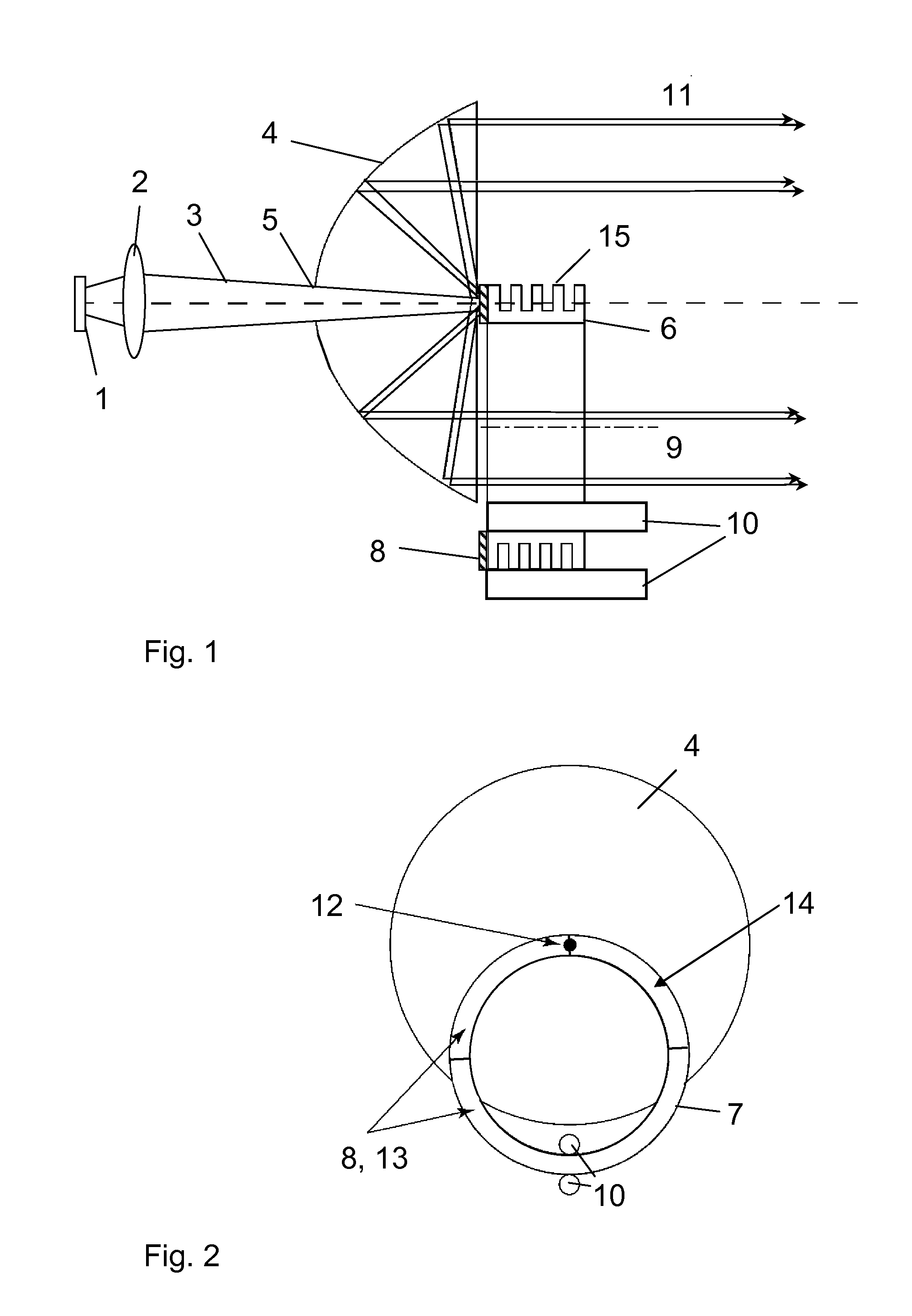
[0018]FIG. 1 shows a schematic side view of an example of the proposed solid state light source in which a rotating ring 6 forms the rotatable support. A reflector 4 is used in combination with a luminescent conversion material 8 which is placed on a side face of the rotating ring 4. An array of laser diodes 1 emits a laser beam of a first wavelength which is focused by a focusing optics 2 onto the ring-shaped side face of the rotating 6 at least partly covered by the luminescent conversion material 8. The reflector 4 comprises a small aperture 5 allowing the passage of the focused laser beam 3.

[0019]Generally, the laser beam can be emitted from a single laser diode or from an array of laser diodes. Typical power levels are in the order of several 10 W, depending on the application.

[0020]The wavelength of the laser diodes can for example be in the range between 360 and 490 nm, where the most common wavelengths are 405 nm (used in Blu-ray optical storage) and around 450 nm, which wav...


PUM


Abstract

The present invention relates to a solid-state light source comprising one or several laser diodes (1) emitting a laser beam with a first wavelength, a rotatable support (6) arranged in a beam path of the laser beam and a reflector (4) arranged between the laser diodes (1) and the rotatable support (6). The rotatable support (6) is formed of a ring or of an optically transparent disc mounted to be rotatable around a rotation axis (9) such that the laser beam impinges on a ring-shaped area (7) of the rotatable support (6) during rotation. One or several segments of the ring-shaped area (7) comprise at least one wavelength converting material (8) emitting radiation of a second wavelength upon impingement of the laser beam. The reflector (4) allows the passage of the laser beam through a central portion of the reflector (4), collects the radiation emitted from a location of impingement of the laser beam on the ring-shaped area (7) and directs the collected radiation to an emission direction. The support (6) is mounted in a bearing (10) arranged distant from the rotation axis (9) to allow unhindered passage of the radiation directed by the reflector (4) to the emission direction. The arrangement of the reflector between the laser diodes and the rotatable support and the location of the bearing for the support distant from the rotation axis allow a compact design of the solid state light source in connection with a high luminescent efficiency.

Description

FIELD OF THE INVENTION[0001]The present invention relates to a solid state light source comprising one or several laser diodes emitting a laser beam with a first wavelength and a rotatable support arranged in a beam path of the laser beam, wherein one or several sections of a ring-shaped area of the rotatable support comprise at least one wavelength converting material emitting radiation of a second wavelength or wavelength region different from the first wavelength upon impingement of the laser beam. Such a solid state light source emitting incoherent high luminance light can be used for a plurality of applications, for example for low Étendue optical systems like light-valve based projection, for spot lighting, for fibre lighting or for architectural lighting applications.BACKGROUND OF THE INVENTION[0002]Solid state light sources are currently entering many different lighting applications and replace incandescent and gas discharge lamps. Several applications are characterized by a...

Claims


Application Information

Patent Timeline
Patent Type & Authority Applications(United States)
IPC IPC(8): F21K99/00F21V29/00F21V13/08
CPCF21K9/56F21Y2101/025F21V29/2206F21V13/08F21S10/007F21V29/502F21V29/74F21K9/64F21Y2115/10F21Y2115/30F21V9/32F21V9/45G02B26/008G03B21/204G03B21/2066G03B33/08F21V29/505
Inventor WEICHMANN, ULRICHPOLLMANN-RETSCH, JENS
Owner SIGNIFY HLDG BV
Learn More