
Optical measuring apparatus

a technology of optical measuring apparatus and optical waveguide, which is applied in the direction of optical radiation measurement, interferometric spectrometry, instruments, etc., can solve the problems of inability to perform measurement using light with an appropriate wavelength, difficult to arbitrarily set the oscillation wavelength, etc., and achieves high intensity light, simple light source, and easy production of long optical waveguides.

Inactive Publication Date: 2008-10-14
FUJIFILM HLDG CORP +1
View PDF2 Cites 1 Cited by
  • Summary
  • Abstract
  • Description
  • Claims
  • Application Information

AI Technical Summary

Benefits of technology

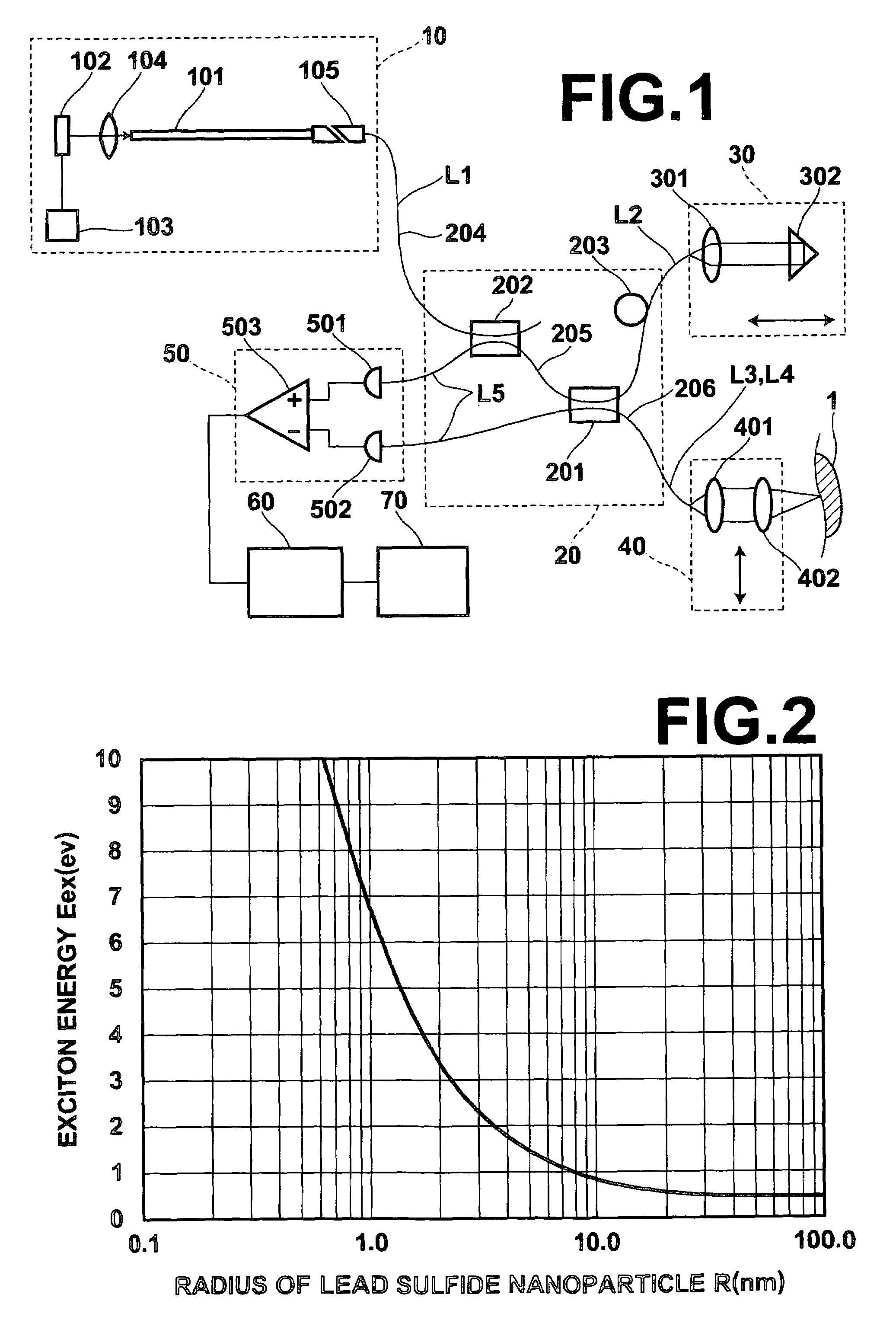
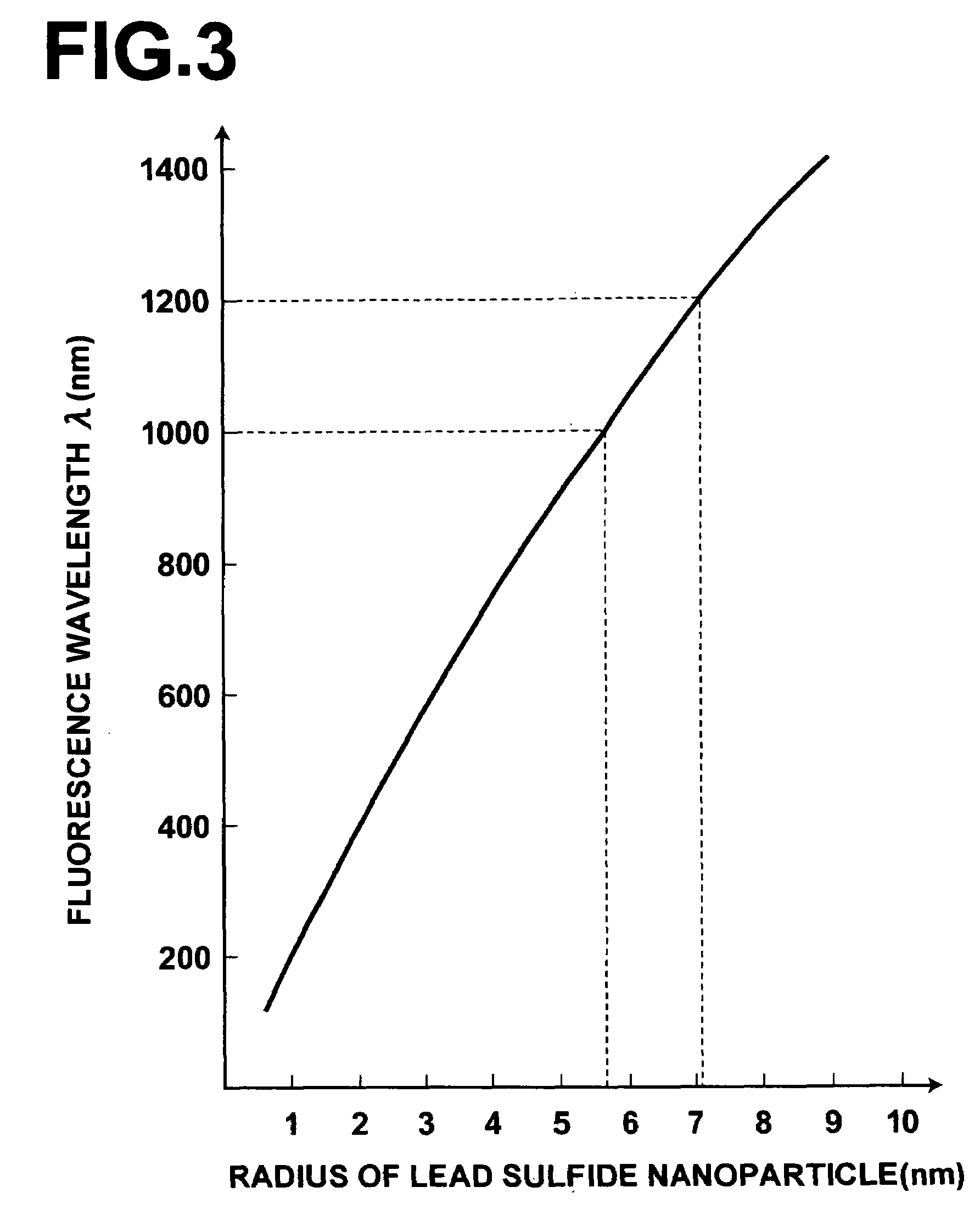
[0031]As the formula (1) indicates, the lowest energy of the inorganic fluorescent nanoparticle is higher than the band gap energy of the bulk crystal, and the smaller the particle diameter, the higher the energy.
[0039]The formula indicates that the resolution of an optical tomographic image in the depth direction is determined mostly by the optical spectral width of the light source. That is, a greater optical spectral width of the light source allows measurement with higher resolution.
[0042]The optical measuring apparatus of the present invention includes an optical element with a plurality of inorganic fluorescent nanoparticles having different fluorescence energy levels dispersed therein as the light source to provide light with an optical spectral width (full width at half maximum) of greater than or equal to 100 nm. In this way, the present invention may realize an optical measuring apparatus which is inexpensive and easy to handle.
[0044]When an optical waveguide is used as the optical element described above, a simple light source may be produced. Further, if an optical fiber having a core made of a polymer or glass material is used as the optical waveguide, a long optical waveguide may be produced easily and thereby high intensity light may be outputted from the light source.
[0045]When the optical measuring apparatus of the present invention includes a branching / combining means for branching the light emitted from the light source into measuring light and reference light, irradiating the measuring light on a test section, and interfering reflected light of the measuring light reflected from a predetermined depth of the test section with the reference light; a measuring means for measuring the light intensity of the interference light produced by the reflected light and reference light; and an image generating means for obtaining an optical tomographic image of the test section based on the light intensity of the interference light obtained by the measuring means, an optical tomographic image may be obtained by the apparatus which is inexpensive and easy to handle.
[0046]Further the light source that includes an optical element with a plurality of inorganic fluorescent nanoparticles having different fluorescence energy levels dispersed therein may realize an optical spectral width of greater than or equal to 100 nm easily.

Problems solved by technology

In the conventional light source that uses a laser, an SLD or the like, however, it is difficult to set the oscillation wavelength arbitrarily because the wavelength of the light emitted from the light source is determined by the composition of the gain medium.
Thus, the optical measuring system using such light source has a problem that it is unable to perform measurement using light with an appropriate wavelength according to the optical transmittance, measuring method employed, or the like.

Method used


Image

  • Optical measuring apparatus
  • Optical measuring apparatus
  • Optical measuring apparatus

Examples


Embodiment Construction

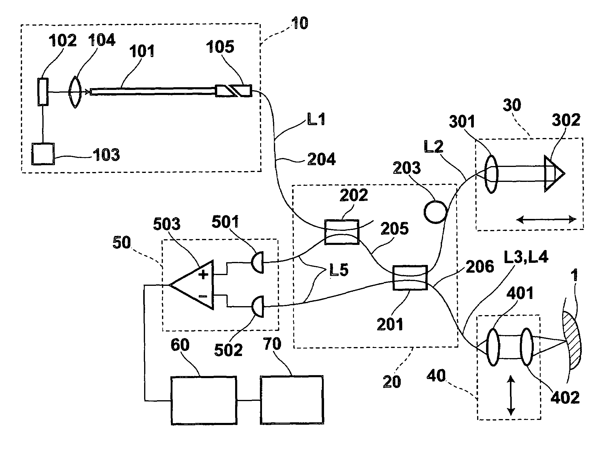
[0050]Hereinafter, an optical tomography imaging apparatus which is a first specific embodiment of the present invention will be described with reference to accompanying drawings. FIG. 1 is a schematic configuration diagram of the optical tomography imaging apparatus of the present invention. The optical tomography imaging apparatus of the present embodiment is an apparatus for obtaining an optical tomographic image of a test section 1, which is living tissue.

[0051]The optical tomography imaging apparatus of the present embodiment includes a light source section 10 for providing broadband low coherence light L1 with a spectral width of 200 nm in the emission range of 1000 nm to 1200 nm; a fiber coupling optical system 20 for branching the low coherence light L1 emitted from the light source section 10 into reference light L2 and measuring light L3, and combining them; an optical path delaying section 30 placed in the optical path of the reference light L2 for changing the optical pa...


PUM


Abstract

Excitation light is inputted to an optical element with uniformly dispersed inorganic fluorescent nanoparticles whose radius is controlled. Fluorescence is emitted from the inorganic fluorescent nanoparticles through photoexcitation and outputted from one end of the optical element. By controlling the radius of the inorganic fluorescent nanoparticles dispersed in the optical element, the wavelength range and spectral width of the light outputted from the optical element are controlled.

Description

BACKGROUND OF THE INVENTION[0001]1. Field of the Invention[0002]The present invention relates to an optical measuring apparatus for measuring characteristics of a test section using light emitted from a light source.[0003]2. Description of the Related Art[0004]Various types of optical measuring systems for measuring characteristic of a test section using light emitted from a light source are known. Optical measurement allows nondestructive testing of semiconductors, disks, living bodies, and the like. For example, optical coherence tomography systems (OCT systems) for obtaining an optical tomographic image of a test section of a living body or the like have already been put into practical use in the medical field or the like. In such systems, the optical tomographic image is obtained by irradiating light on the test section and using the light reflected from or transmitted through the test section.[0005]Various types of OCT systems have been developed. An OTDR (optical time domain r...

Claims


Application Information

Patent Timeline
Patent Type & Authority Patents(United States)
IPC IPC(8): G01B9/02G01J3/45
CPCG01J3/02G01J3/0218G01J3/10G01N21/4795G01N2201/06193
Inventor HIIRO, HIROYUKI
Owner FUJIFILM HLDG CORP
Learn More