Multilayered distributed router architecture

a distributed router and router technology, applied in the field of data forwarding, can solve the problems of complex and inflexible router programming in a huge network (e.g., the internet), which may comprise tens of thousands of such routers, and lack of flexibility and dynamic configurability of network applications such as cloud computing and mobile computing, and achieve the flexibility and dynamic configurability desired by today's (and tomorrow's) network applications

Active Publication Date: 2016-06-16
CIENA
View PDF4 Cites 50 Cited by
  • Summary
  • Abstract
  • Description
  • Claims
  • Application Information

AI Technical Summary

Benefits of technology

[0020]The foregoing, together with other features and embodiments will become more apparent upon referring to the following specification, claims, and accompanying drawings.

Problems solved by technology

This makes programming of such routers in a huge network (e.g., the Internet), which may comprise tens of thousands of such routers, complicated and inflexible.
This per router-centric management requirement makes management of such networks very complex and time consuming.
As a result, networks using conventional routers lack the flexibility and dynamic configurability desired by today's (and tomorrow's) network applications such as cloud computing, mobile computing, real-time and on-demand video traffic, and the like.

Method used


Image

  • Multilayered distributed router architecture
  • Multilayered distributed router architecture
  • Multilayered distributed router architecture

Examples


Embodiment Construction

[0028]In the following description, for the purposes of explanation, specific details are set forth in order to provide a thorough understanding of embodiments of the invention. However, it will be apparent that various embodiments may be practiced without these specific details. The figures and description are not intended to be restrictive. The word “exemplary” is used herein to mean “serving as an example, instance, or illustration.” Any embodiment or design described herein as “exemplary” is not necessarily to be construed as preferred or advantageous over other embodiments or designs.

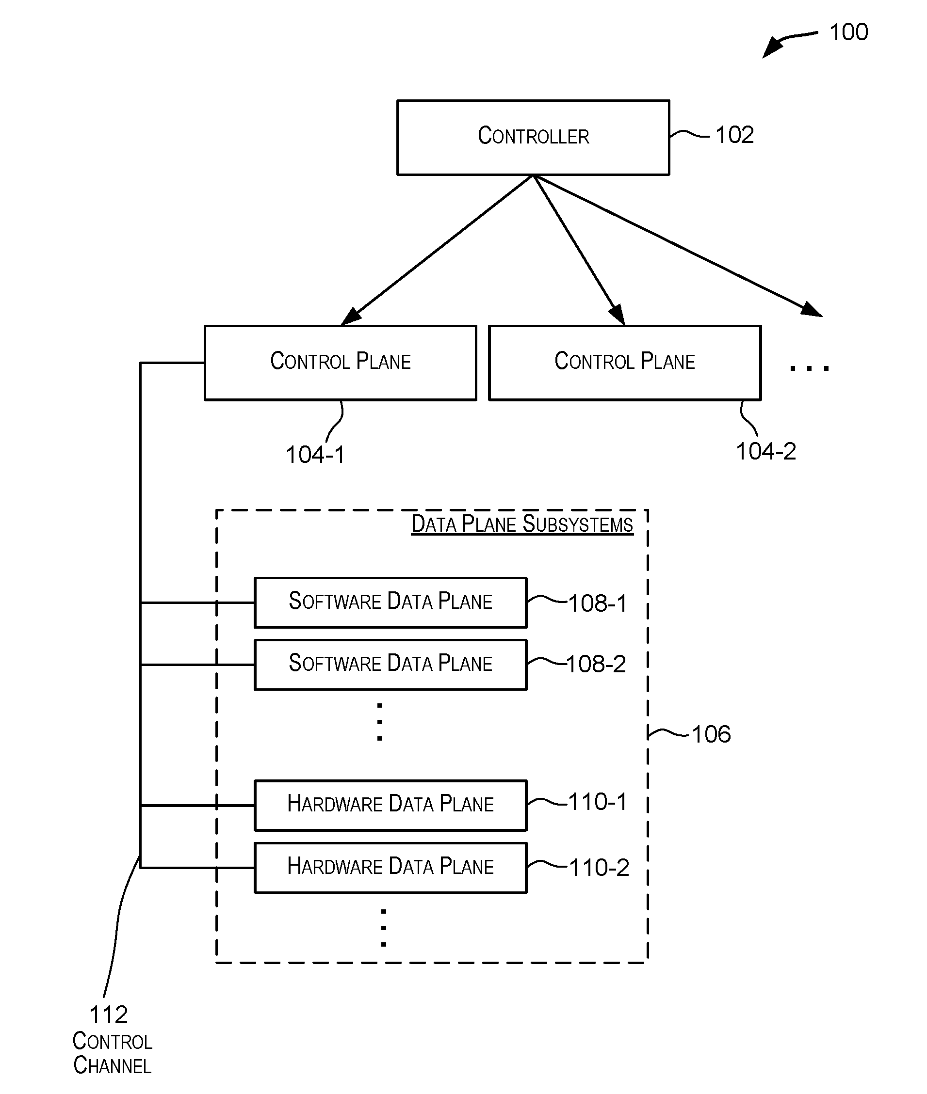
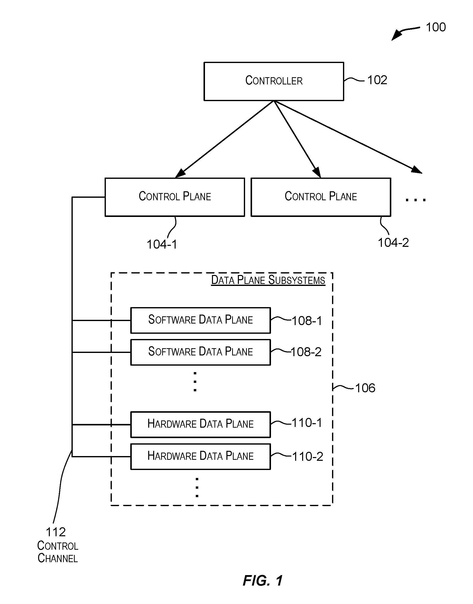
[0029]The present disclosure relates to data forwarding, and more particularly to a distributed multilayered network router architecture. FIG. 1 is a simplified block diagram illustrating a distributed multilayered router architecture 100 according to an embodiment of the present invention. The embodiment depicted in FIG. 1 is merely an example and is not intended to unduly limit the claimed embodi...


PUM


Abstract

A distributed multilayered network routing architecture comprises multiple layers including a controller layer comprising a controller, a control plane layer comprising one or more control plane subsystems, and a data plane layer comprising one or more data plane subsystems. A controller may be coupled to one or more control plane subsystems. A control plane subsystem may in turn be coupled to one or more data plane subsystems, which may include one or more software data plane subsystems and/or hardware data plane subsystems. In certain embodiments, the locations of the various subsystems of a distributed router can be distributed among various devices in the network.

Description

CROSS-REFERENCES TO RELATED APPLICATIONS[0001]The present application is a non-provisional of and claims the benefit and priority under 35 U.S.C. 119(e) of U.S. Provisional Application No. 62 / 090,627, filed Dec. 11, 2014, entitled “MULTI-LAYER ACCELERATED NETWORK ARCHITECTURE”, the entire contents of which are incorporated herein by reference for all purposes.BACKGROUND[0002]The present disclosure relates to data forwarding, and more particularly to a multilayered distributed router architecture.[0003]A router is a specialized network device that is configured to forward data (e.g., data packets) between networks to facilitate the delivery of the data from its source to its intended destination. A router is configured to determine optimal routes or data paths through an internetwork topology and transport data packets using these optimal paths. A router also provides various other services such as firewall, Quality of Service (QoS), and the like.[0004]A conventional router typically...

Claims


Application Information

Patent Timeline
Patent Type & Authority Applications(United States)
IPC IPC(8): H04L12/773H04L12/931H04L45/42H04L45/60
CPCH04L49/602H04L45/60H04L45/42
Inventor BAYS, ROBERT
Owner CIENA
Why Eureka
Try Eureka