Handoff procedure in a mobile communication system

a mobile communication system and handoff procedure technology, applied in the field of handoff procedures in mobile communication systems, can solve the problems of difficult to successfully receive the handoff command by the ue, complex preventive solutions in the state-of-the-art, and not completely clear how, so as to improve the reliability and robustness of the decision to handoff to the target base station

Active Publication Date: 2016-06-16
PANASONIC INTELLECTUAL PROPERTY CORP OF AMERICA
View PDF0 Cites 95 Cited by
  • Summary
  • Abstract
  • Description
  • Claims
  • Application Information

AI Technical Summary

Benefits of technology

[0104]One object of the invention is to provide an improved method for performing a handoff of a mobile terminal to a target base station. More specifically, in performing the handoff the mobile terminal remains under the control of the target base station, while at the same time robustness and reliability of the decision to handoff to the target base station is improved.
[0112]This separation is advantageous in view of an optimal timing of the handoff: The mobile terminal may delay or defer execution of the handoff to the target base station up to a point in time where its connectivity (e.g. to the source radio cell) is lost. In this respect, a handoff to the target base station may be delayed or deferred up to a point in time where reception of the handoff command message would no longer be possible. Accordingly, the invention strives to prevent from too early handoffs by solving the problem of too late handoffs (i.e. lost handoff command messages due to poor radio conditions in the source radio cell).

Problems solved by technology

This is mainly so since the radio condition in the Small / Pico cell's edge is weaker and interfered by the Macro cells transmissions.
In these situations it is difficult to successfully receive the handover command by the UE.
The preventive solutions in the state-of-the-art are quite complex and in some cases not completely clear how these will work; for example:
Repetition of HO CMD message by cells other than the source cell (RRC Diversity) e.g. the handover target cell requires that the UE be able to receive from 2 different cells [Simultaneous or One by one] and it will be unattractive and complex since:Simultaneous reception requires dual connection capability which may not be available with all UEs and dual connectivity itself may not be a desirable solution in some deployment scenarios (e.g. in Scenario 1 of SCE).One by one (first by source and then by target): In this case, it is not clear when and how will the UE know, which C-RNTI to use, which SRB configuration to use etc. when trying to receive the HO CMD from the Target Cell.
However, this alone is not sufficient for non ideal ABS coordination among macro cells and larger CRE bias cases.
The curative methods are not sufficient since they lead to more complexity (in enhancing Re-establishment) and still cause some jitters.
Another problem in Heterogeneous deployment is the UE battery consumption in:1) Finding / discovering the small cell layer since these small cells may not be ubiquitously present everywhere.2) Measuring 2 source frequencies while in dual connectivity which might be un-necessary sometimes.

Method used


Image

  • Handoff procedure in a mobile communication system
  • Handoff procedure in a mobile communication system
  • Handoff procedure in a mobile communication system

Examples


first embodiment

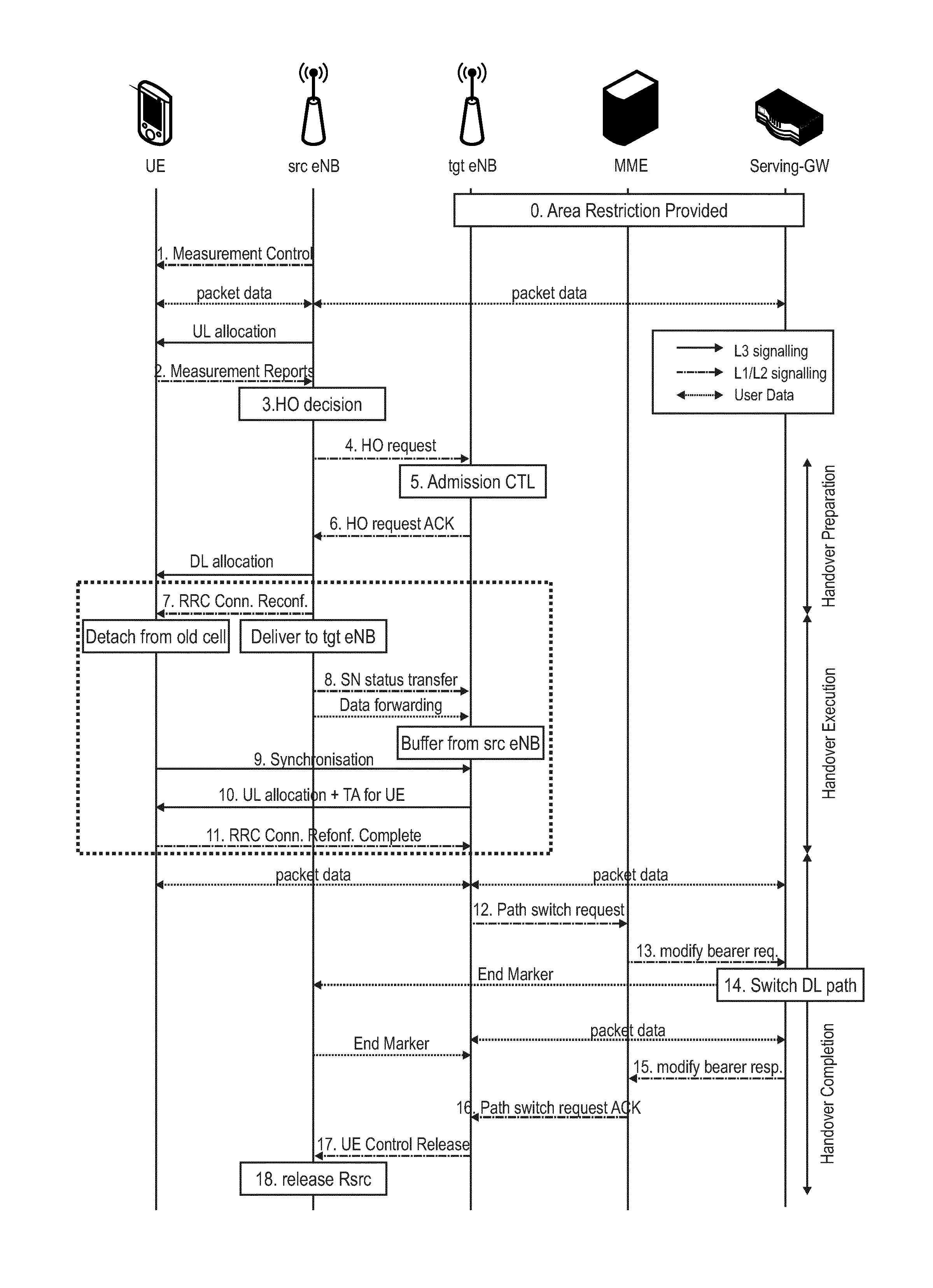
[0191]Referring now to the first embodiment of the invention, various implementations of an improved handover procedure are to be discussed in connection with FIGS. 11 to 14. Specifically, FIG. 11 illustrates a sequence diagram of the handover procedure to a target base station to be performed by a mobile terminal.

[0192]In the context of the first embodiment, it is assumed that the mobile terminal is initially configured for communication with a source base station via a source radio cell. The mobile terminal is in the RRC CONNECTED state with respect to the source radio cell. The mobile terminal then performs the handover procedure for it to be configured for communication with the target base station via a target radio cell. As a result of successful completion of the handover procedure, the mobile terminal detaches from the source radio cell, and remains in the RRC CONENCTED state with respect to the target radio cell.

[0193]The handover procedure is performed under control of the...

second embodiment

[0243]Referring now to the second embodiment of the invention, various implementations of improved configurations of measurement cycles are to be discussed in connection with FIGS. 15 to 16. Specifically, FIG. 15 illustrates a sequence diagram of the configuration of measurement cycles of a mobile terminal by a master base station.

[0244]In the context of the second embodiment it is assumed that the mobile terminal, for which the measurement cycles are configured by the master base station, is connected via a macro radio cell to the master base station and via a small radio cell to the secondary base station.

[0245]For configuration of the measurement cycles, the master base station, according to the second embodiment, determines (c.f. Step S1501 in FIG. 15) a geographical distance between the master base station and the secondary base station both serving the mobile terminal. As already pointed out at the beginning of the detailed description, the term path loss may be used as an equ...


PUM


Abstract

The invention relates to an improved handover procedure for a mobile terminal. Under control of the target base station, the mobile terminal is to perform a handoff to a target base station, wherein it is to be configured for communication with the target base station via a target radio cell comprising a downlink carrier and an uplink carrier. The mobile terminal receives a handoff command message for the handoff to the target base station including a handoff execution condition as trigger for executing handoff to the target base station. Then, the mobile terminal determines, based on the received handoff execution condition, whether or not the mobile terminal is to trigger execution of the handoff to the target base station. In case the mobile terminal determines that it is to trigger execution of the handoff to the target base station, the mobile terminal executes the handoff to the target base station.

Description

FIELD OF THE INVENTION[0001]The invention relates to methods for performing a handoff of a mobile terminal to a target base station. As part of the handoff, the mobile terminal is to be configured for communication with the target base station via a target radio cell comprising a downlink and an uplink carrier. The invention also provides the mobile terminal and the base station for performing the methods described herein.TECHNICAL BACKGROUNDLong Term Evolution (LTE)[0002]Third-generation mobile systems (3G) based on WCDMA radio-access technology are being deployed on a broad scale all around the world. A first step in enhancing or evolving this technology entails introducing High-Speed Downlink Packet Access (HSDPA) and an enhanced uplink, also referred to as High Speed Uplink Packet Access (HSUPA), giving a radio access technology that is highly competitive.[0003]In order to be prepared for further increasing user demands and to be competitive against new radio access technologies...

Claims


Application Information

Patent Timeline
Patent Type & Authority Applications(United States)
IPC IPC(8): H04W36/30H04W74/08H04W74/00H04W36/00
CPCH04W36/30H04W74/006H04W74/0833H04W36/0005H04W36/0072
Inventor BASU MALLICK, PRATEEKLOEHR, JOACHIM
Owner PANASONIC INTELLECTUAL PROPERTY CORP OF AMERICA
Why Eureka
Try Eureka