

Power supply device and method for plasma generation
- Summary
- Abstract
- Description
- Claims
- Application Information
AI Technical Summary
Benefits of technology
Problems solved by technology
Method used
Image

Examples
first embodiment
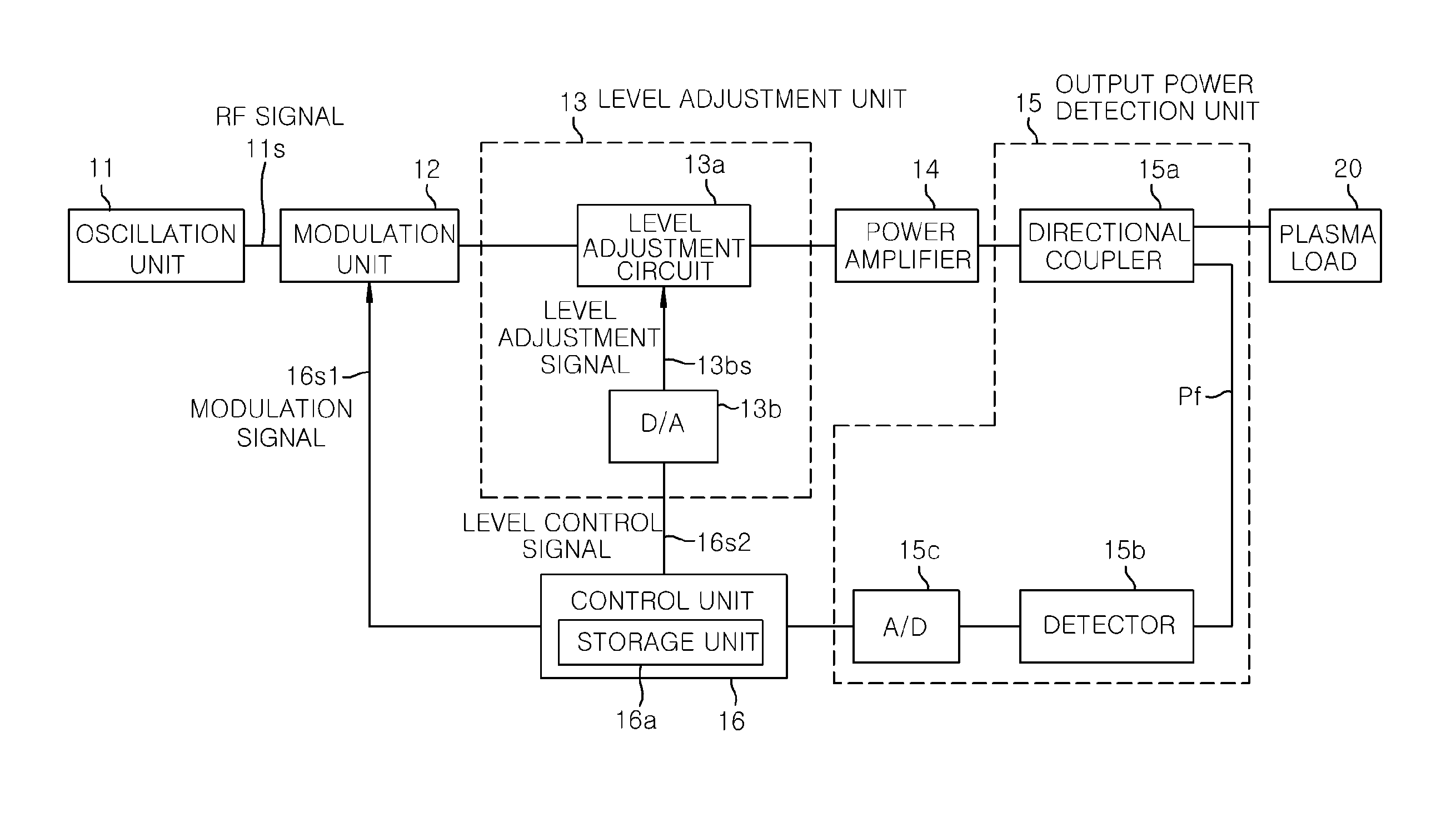
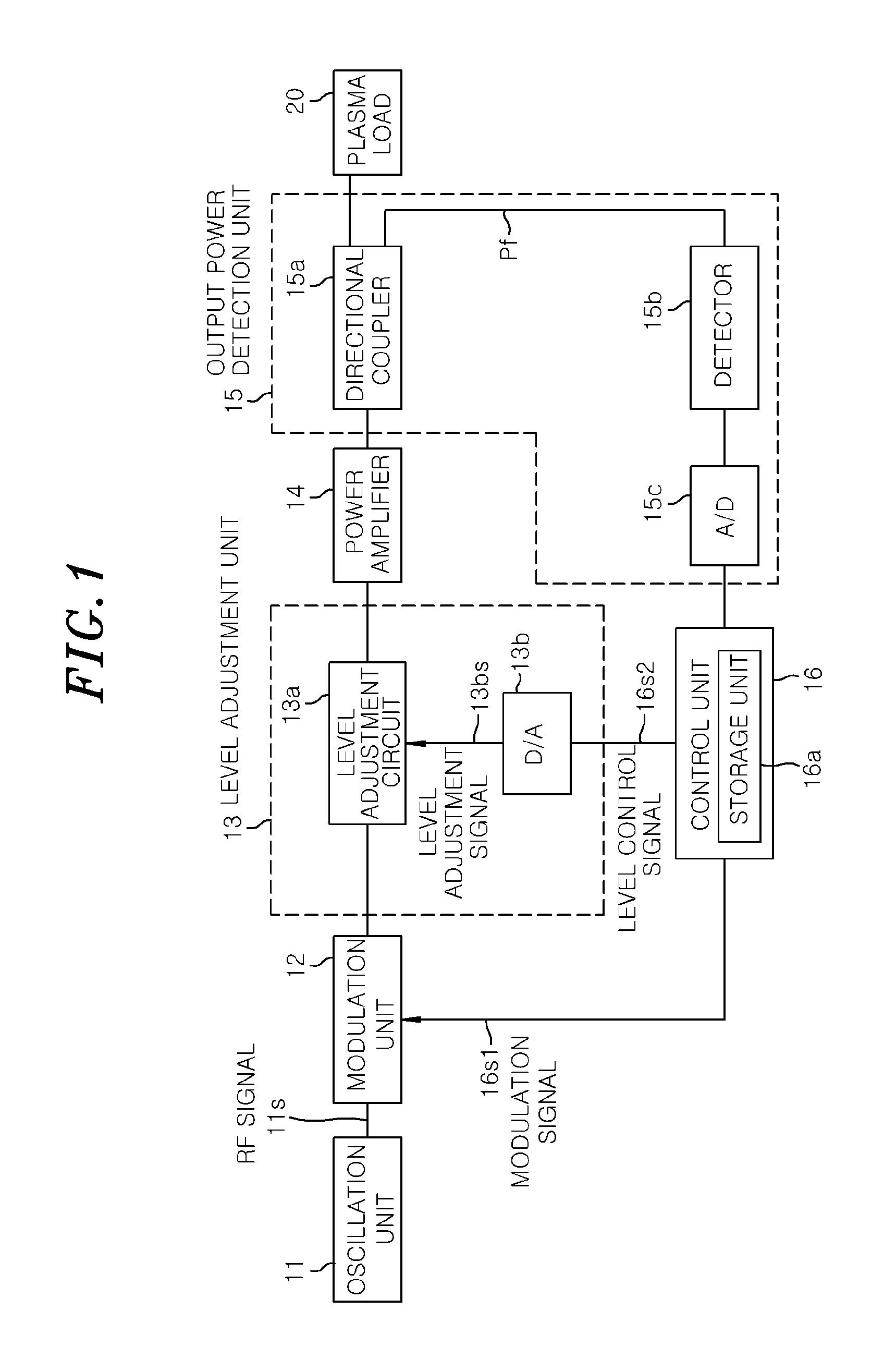
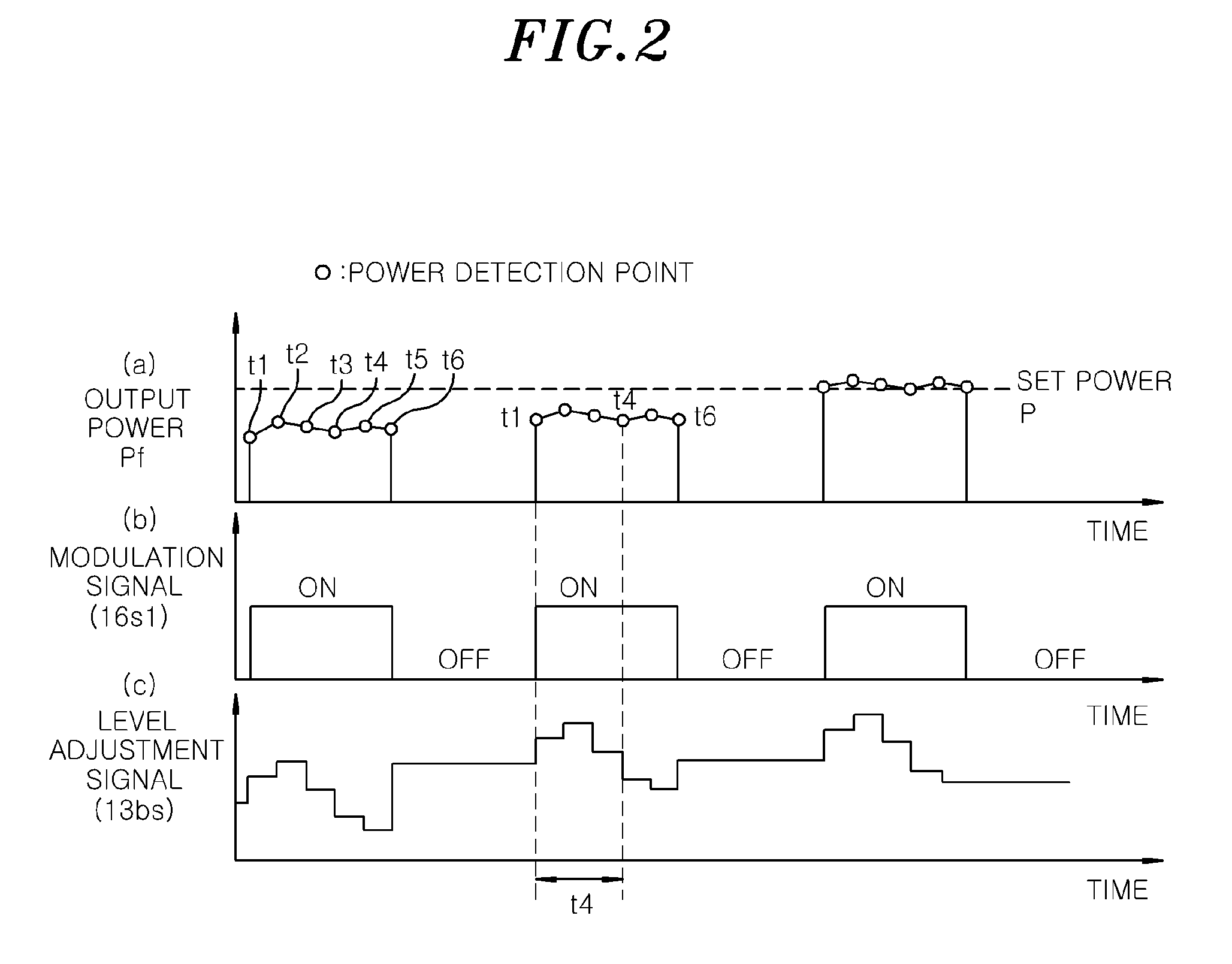
[0029]The present inventors have found that after supplying power to a plasma load 20 by turning on a pulsed modulation signal 16s1, an output power value varies with the lapse of time, and the fluctuations of the output power value are repeated in the same pattern when the plasma load 20 has the same property. For example, the fluctuation pattern of the output power value is identical in the same plasma generating apparatuses. In a first embodiment, the present inventors have paid attention to a phenomenon in which the output power varies in the same pattern as time goes by after the pulsed modulation signal 16s1 is turned on. In the first embodiment, an output power within an on-period of the modulation signal 16s1 is controlled to become a constant value by correcting a level adjustment signal 13bs in each elapsed time.
[0030]The first embodiment of the present invention will be described with reference to FIGS. 1 to 3. FIG. 1 is a block diagram showing a functional configuration ...
second embodiment
[0056]Next, a second embodiment of the present invention will be described. A functional configuration of a high frequency power supply device in the second embodiment is equal to that in the first embodiment, except a configuration of the control unit 16. In the second embodiment, the control unit 16 operates to frequently update the correction factor B. Specifically, the control unit 16 compares the set power value Ps and the output power Pf at each elapsed time t in a pulse-on state (on-state of the modulation signal 16s1), and updates the correction factor B such that a difference Pd between the set power value Ps and the output power Pf becomes smaller than a difference Pd′ in a previous pulse-on state at each elapsed time t.
[0057]An output power level adjusting method in accordance with the second embodiment will be described in detail with reference to a flow chart of FIGS. 4A and 4B. FIGS. 4A and 4B are a flow chart showing the output power level adjusting method in accordan...
third embodiment
[0077]A difference of a third embodiment from the first and second embodiments will be described. In the first and second embodiments, the correction factor B1 is read out from a table that is previously set. However, the correction factor B1 may be frequently updated. In the third embodiment, a comparison value in a current pulse and a comparison value in a previous pulse are compared with each other and the correction factor B1 is updated such that the comparison result between a set power P and the output power Pf becomes smaller at each reflection coefficient F. The control flow chart is only changed and a configuration of the device is the same as those in the first and second embodiments.
[0078]A flowchart of a control method in accordance with the third embodiment is shown in FIGS. 7A and 7B. First, in step S201, an initial setting is performed. A set power P and a power range are set in the initial setting. If the modulation signal is off in step S202, the process does not pr...
PUM
 Abstract
Description
Claims
Application Information