Equalizing filter circuit

a filter circuit and equalization technology, applied in the field of equalization filter circuits, can solve the problems of difficult high-precision compensation control, partial mismatch of transmission line impedance, and difficulty in adapting equalization according to dynamic waveform distortion

Inactive Publication Date: 2012-05-01
NEC CORP
View PDF6 Cites 0 Cited by
  • Summary
  • Abstract
  • Description
  • Claims
  • Application Information

AI Technical Summary

Benefits of technology

[0012]Accordingly, the present invention has been made to solve the above problems associated with the prior art, and it is an object of the present invention to provide an equalizing filter circuit which can suppress fluctuation of the output characteristics of the weighting circuits and the delay characteristics of the delay devices and can perform stable and high-precision compensation for signal waveform distortion although the arbitrary setting of the coefficients of the weighting circuits has been made performed.
[0015]According to the present invention, the variable adjusting circuit performs the operation of canceling a fluctuation of an output load of an amplifier of the weighting circuit that occurs when the coefficient of the amplifier is changed so that a change of the delay time of the delay devices or an impedance mismatch can be suppressed. As a result, performing stable and high-precision compensation control for signal waveform distortion is realized so that an adaptive equalization according to dynamic waveform distortion becomes easier.

Problems solved by technology

However, the transversal filter encounters a problem in which since it uses the transmission line as the delay devices, the length of the transmission line is determined depending on the delay time, for which reason the circuit configuration that uses impedance matching through optimization of the transmission line can be employed.
Furthermore, the transversal filter entails a drawback in which since the gain-weighting amplifiers thereof arbitrarily set respective weighting coefficients, the output loads of respective weighting circuits vary depending on the set coefficient values, leading to a partial change in the delay time of the delay devices, and the impedance of the transmission line is partially mismatched.
That is, when the weighting coefficients of the weighting circuits are changed, the frequency characteristics and the set delay time of the delay devices are changed to make high-precision control of compensation difficult, resulting in a significant difficulty in compensation according to dynamic changes and adaptive equalization.

Method used


Image

  • Equalizing filter circuit
  • Equalizing filter circuit
  • Equalizing filter circuit

Examples


first example

The First Example

[0044]In this example, the variable adjusting circuit adjusts the output load of the weighting circuits through the operation thereof in response to changing the coefficient of the weighting circuits.

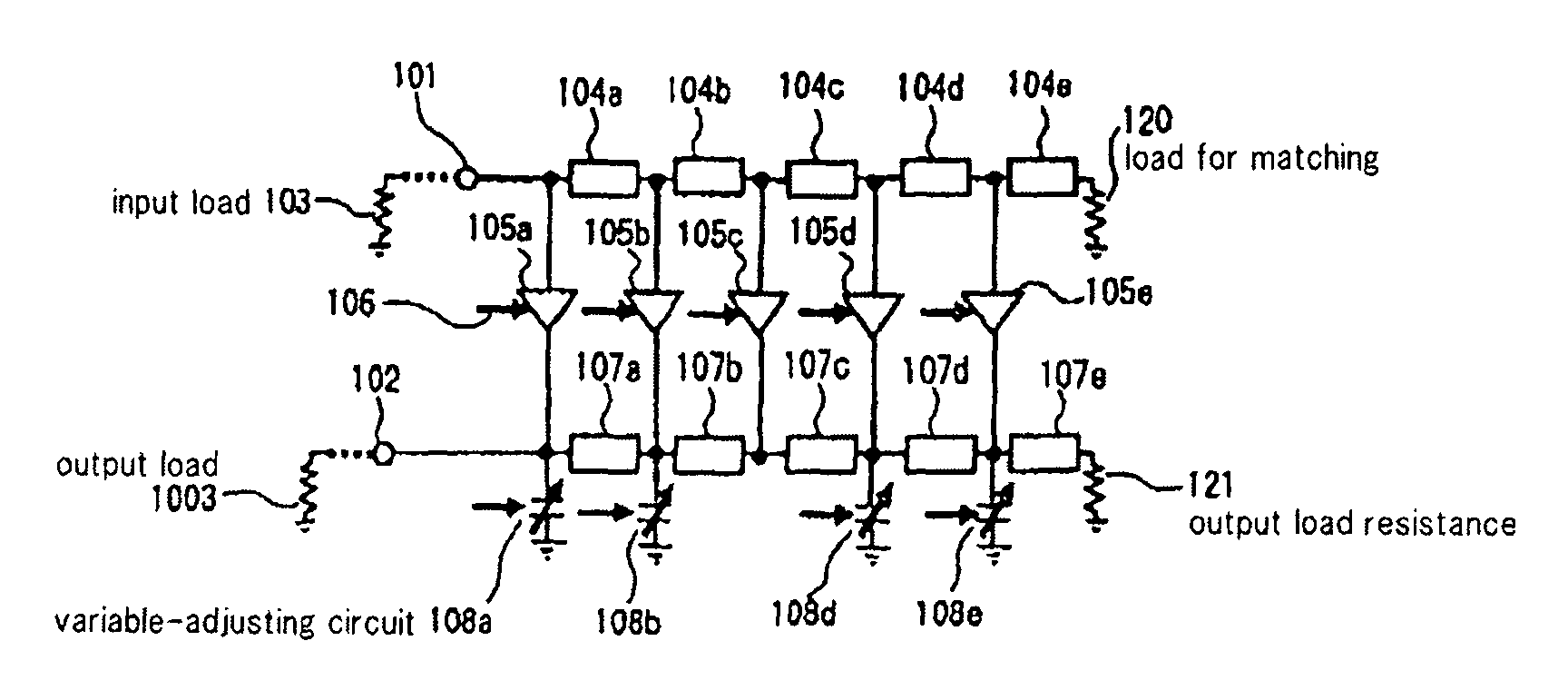
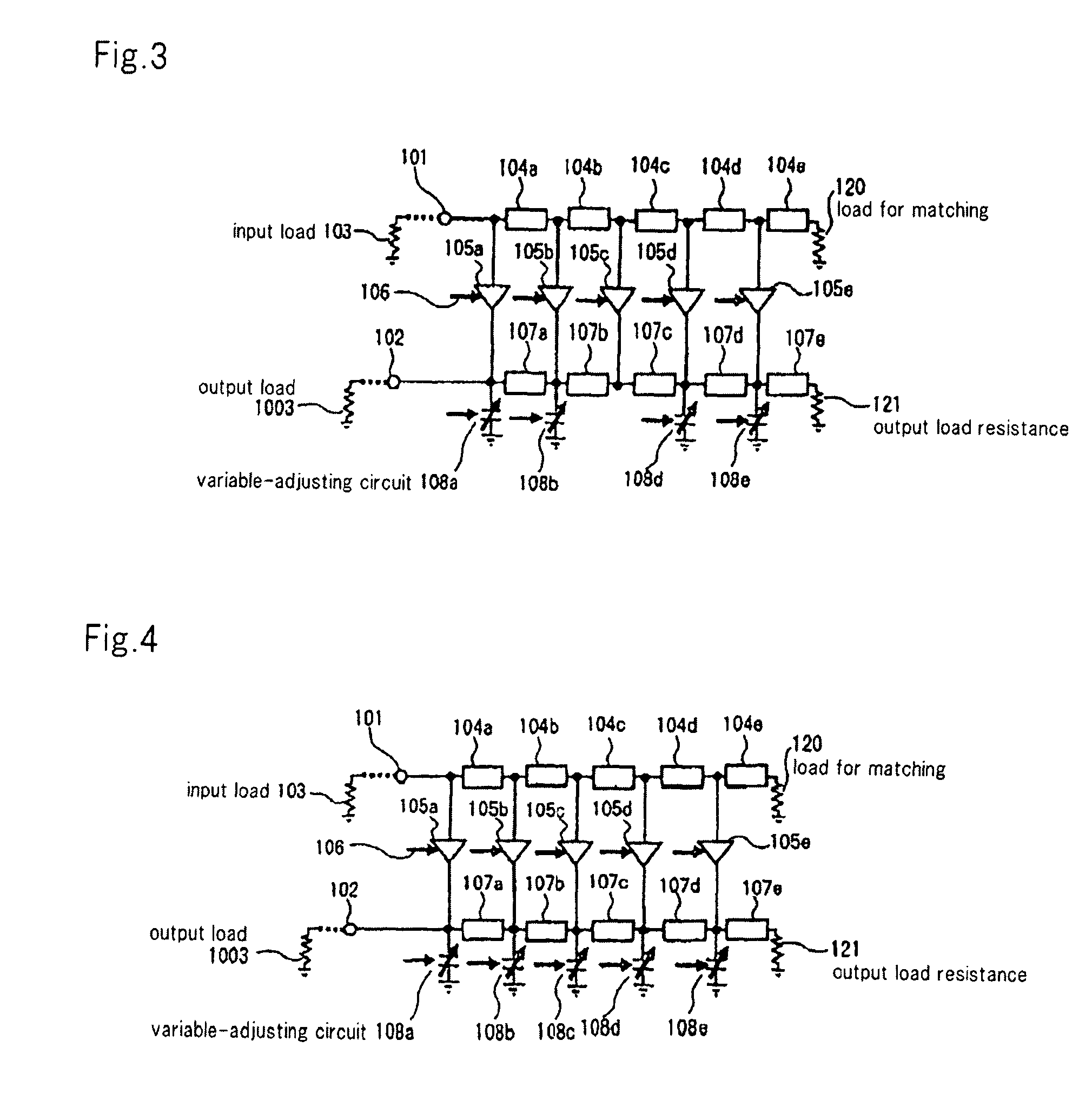
[0045]The configuration of the equalizing filter circuit according to this example will be described hereinafter. In the meantime, the same elements as those in the configuration shown in FIG. 3 are denoted by the same reference numerals, and a detailed description of the configuration will be omitted.

[0046]FIG. 5 is a circuit block diagram illustrating a configuration of an equalizing filter circuit according to a first example of the present invention.

[0047]As shown in FIG. 5, the equalizing filter circuit according to the first example of the present invention includes a plurality of delay devices 104a to 104e connected in cascade to filter input terminal 101, a plurality of weighting circuits 205a to 205e having an adjustable gain, and a plurality of delay devices 1...

second example

The Second Example

[0063]In this example, the capacitance elements included in the delay devices are configured as parts of the variable adjusting circuits.

[0064]The configuration of the equalizing filter circuit according to this example will be described hereinafter.

[0065]In the meantime, the same elements as those in the configuration shown in FIG. 3 are denoted by the same reference numerals, and a detailed description of the configuration will be omitted.

[0066]FIG. 10 is a circuit block diagram illustrating a configuration of an equalizing filter circuit according to a second example of the present invention.

[0067]As shown in FIG. 10, the equalizing filter circuit according to the second example of the present invention includes a plurality of delay devices 104a to 104e connected in cascade to filter input terminal 101, a plurality of weighting circuits 705a to 705e having an adjustable gain, and a plurality of delay devices 707a to 707e connected in cascade to filter output ter...

third example

The Third Example

[0077]The configuration of the equalizing filter circuit according to this example will be described hereinafter. In the meantime, the same elements as those in the configuration shown in FIG. 3 are denoted by the same reference numerals, and its detailed description will be omitted.

[0078]FIG. 14 is a circuit block diagram illustrating a configuration of an equalizing filter circuit according to a third example of the present invention.

[0079]As shown in FIG. 14, the equalizing filter circuit according to the third example of the present invention includes a plurality of delay devices 104a to 104e connected in cascade to filter input terminal 101, a plurality of weighting circuits 705a to 705e having an adjustable gain, and a plurality of delay devices 707a to 707e connected in cascade to filter output terminal 102.

[0080]Each of variable adjusting circuits 708a to 708e including the varactor element is connected to each output side of weighting circuits 705a to 705e....


PUM


Abstract

An equalizing filter circuit includes a first transmission line in which a plurality of first delay devices 104a are connected in cascade to input terminal 101, a second transmission line in which a plurality of second delay devices 107a are connected in cascade to output terminal 102, a plurality of weighting circuits 105a connected in parallel between the first transmission line and the second transmission line and having a gain which is adjustable by setting coefficients, and variable adjusting circuit 108a arranged at the output side of at least one of weighting circuits 105a for correcting a fluctuation of the output characteristics of the weighting circuits.

Description

[0001]This application is the National Phase of PCT / JP2007 / 066460, filed Aug. 24, 2007, and is based upon and claims the benefit of priority from Japanese Patent Application No. 2006-235520, filed on Aug. 31, 2006, the disclosure of which is incorporated herein in its entirety by reference.TECHNICAL FIELD[0002]The present invention relates to a signal processing circuit, and more particularly, to an equalizing filter circuit, which compensates for distortion of a signal waveform generated in a transmission medium, in an optical communication using an optical fiber, in a telecommunication using wires, and in a wireless communication.BACKGROUND ART[0003]In a variety of transmission systems, a weighted and delayed equalizing filter circuit is frequently employed as a technological means for electrically compensating for waveform distortions that are generated due to dispersion or loss in a transmission medium.[0004]FIG. 1 is a circuit block diagram of a conventional weighted and delaye...

Claims


Application Information

Patent Timeline
Patent Type & Authority Patents(United States)
IPC IPC(8): H03H7/30
CPCH03H15/00H04B3/142H04B3/145H03H2015/007
Inventor WADA, SHIGEKI
Owner NEC CORP
Why Eureka
Try Eureka