Gas turbine engine with angularly offset turbine vanes

a technology of turbine vanes and turbine blades, which is applied in the direction of turbine/propulsion fuel flow conduits, combustion processes, lighting and heating apparatus, etc., can solve the problems of vibration stress in the rotating parts of the turbine section, and achieve the effect of reducing vibration stress

Inactive Publication Date: 2016-06-23
PRATT & WHITNEY CANADA CORP
View PDF9 Cites 4 Cited by
  • Summary
  • Abstract
  • Description
  • Claims
  • Application Information

AI Technical Summary

Benefits of technology

[0005]In a further aspect, there is provided a method of reducing vibratory stresses in a turbine disposed downstream of a plurality of fuel nozzles of a gas turbine engine, the turbine including a rotor disposed immediately downstream from a stator, the method comprising: positioning the vanes of the stator angularly offset in a circumferential direction relative to the fuel nozzles, the fuel nozzles forming pressure pulses of fluid and the angular offsetting disposing the vanes in flowpaths of the pressure pulses, the fuel nozzles being arranged circumferentially equidistant from one another about a first center, the vanes being arranged circumferentially equidistant from one another about a second center, the angular offsetting being assessed when projecting the second center onto the first center.

Problems solved by technology

The pressure pulses associated to the hot and cold pulses may cause vibratory stresses in the rotating parts of the turbine section.

Method used


Image

  • Gas turbine engine with angularly offset turbine vanes
  • Gas turbine engine with angularly offset turbine vanes
  • Gas turbine engine with angularly offset turbine vanes

Examples


Embodiment Construction

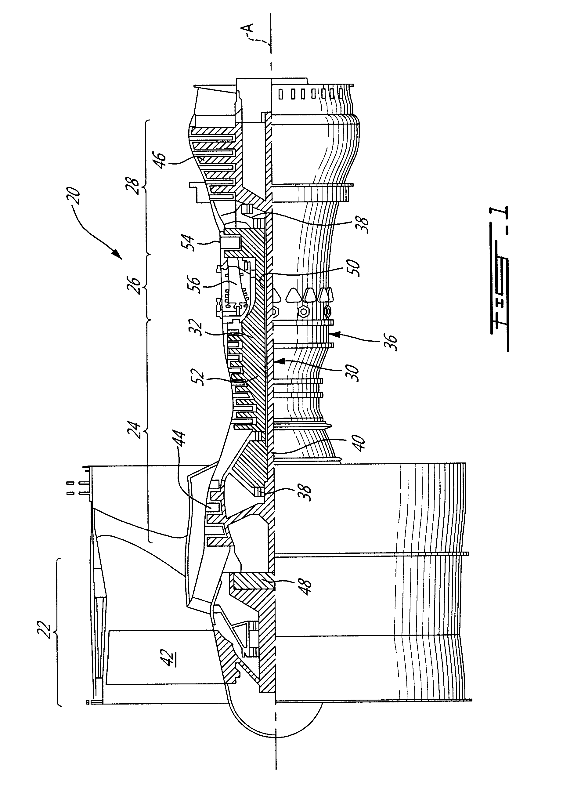
[0015]FIG. 1 schematically illustrates a gas turbine engine 20. The gas turbine engine 20 is disclosed herein as a two-spool turbofan that generally incorporates a fan section 22, a compressor section 24, a combustor section 26 and a turbine section 28. Alternative engines might include an augmentor section (not shown) among other systems or features. The fan section 22 drives air along a bypass flowpath while the compressor section 24 drives air along a core flowpath for compression and communication into the combustor section 26 then expansion through the turbine section 28. Although depicted as a turbofan gas turbine engine in the disclosed non-limiting embodiment, it should be understood that the concepts described herein are not limited to use with turbofans as the teachings may be applied to other types of turbine engines such as a three-spool (plus fan) engine wherein an intermediate spool includes an intermediate pressure compressor (IPC) between the LPC and HPC and an inter...


PUM


Abstract

A gas turbine engine includes a combustor having a plurality of fuel nozzles arranged circumferentially equidistant from one another about a first center. The plurality of fuel nozzles produce a plurality of pressure pulses in a fluid contained in the combustor. A turbine section is disposed downstream of the combustor and receiving the fluid from the combustor. The turbine section includes a plurality of vanes arranged circumferentially equidistant from one another about a second center. When projecting the second center onto the first center, the plurality of vanes is angularly offset in a circumferential direction relative to the plurality of fuel nozzles of a predetermined amount. The offsetting positions the vanes in flowpaths of the pressure pulses generated by the plurality of fuel nozzles.

Description

TECHNICAL FIELD[0001]The application relates generally to gas turbine engines and, more particularly, to arrangements between fuel nozzles and vanes downstream thereof.BACKGROUND[0002]Gas turbine engines generally include a compressor section to pressurize an airflow, a combustor for burning a hydrocarbon fuel in the presence of the pressurized air, and a turbine section for extracting energy from the resultant combustion gases. A plurality of circumferentially distributed fuel nozzles project into the combustor to supply the fuel to be mixed with the pressurized air. The fuel nozzles produce a plurality of alternating hot and cold pulses (a.k.a. streaks) in the fluid contained in the combustor. The hot and cold pulses are moved downstream through the turbine section. The pressure pulses associated to the hot and cold pulses may cause vibratory stresses in the rotating parts of the turbine section.SUMMARY[0003]In one aspect, there is provided a gas turbine engine comprising: a combu...

Claims


Application Information

Patent Timeline
Patent Type & Authority Applications(United States)
IPC IPC(8): F02C7/22F23R3/28
CPCF02C7/222F05D2240/24F05D2220/32F23R3/286F01D9/023F01D9/041F02C3/14F23R3/50F05D2260/961
Inventor TARDIF, MARCRONDEAU, JACINTHEDI FLORIO, DOMENICO
Owner PRATT & WHITNEY CANADA CORP
Why Eureka
Try Eureka