Eureka AIR delivers breakthrough ideas for toughest innovation challenges, trusted by R&D personnel around the world.

Heat dissipating module having turbulent structures

a technology of heat dissipation module and turbulent structure, which is applied in the direction of indirect heat exchangers, lighting and heating apparatus, instruments, etc., can solve the problems of increasing the weight and volume of the projection device, increasing the noise, and reducing the convenience and safety of installation and use of the projection device. , to achieve the effect of improving the heat dissipation efficiency

Active Publication Date: 2016-06-23
CORETRONIC
View PDF2 Cites 7 Cited by
  • Summary
  • Abstract
  • Description
  • Claims
  • Application Information

AI Technical Summary

Benefits of technology

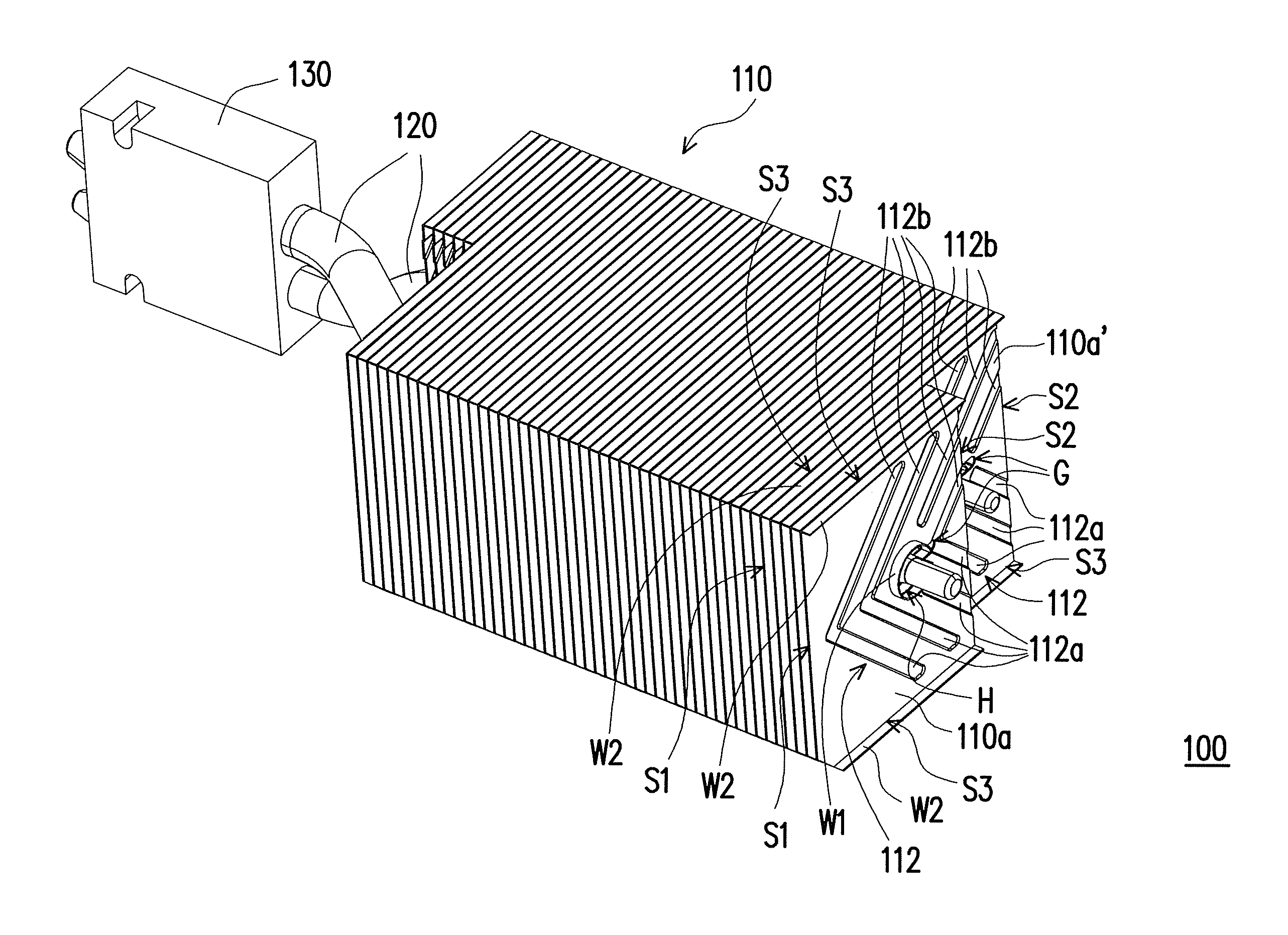
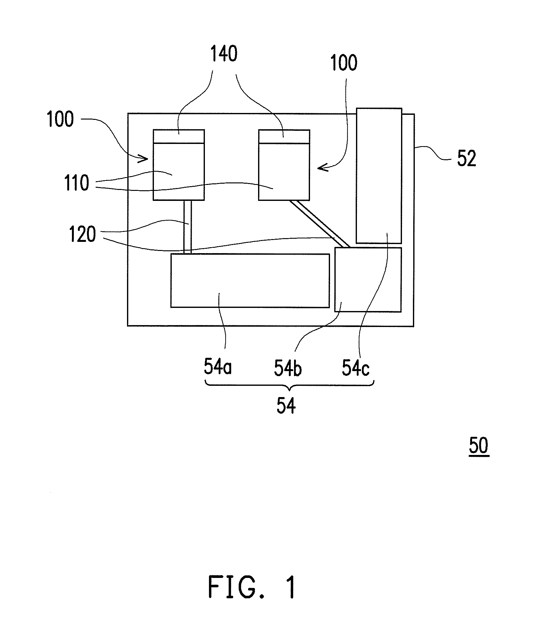
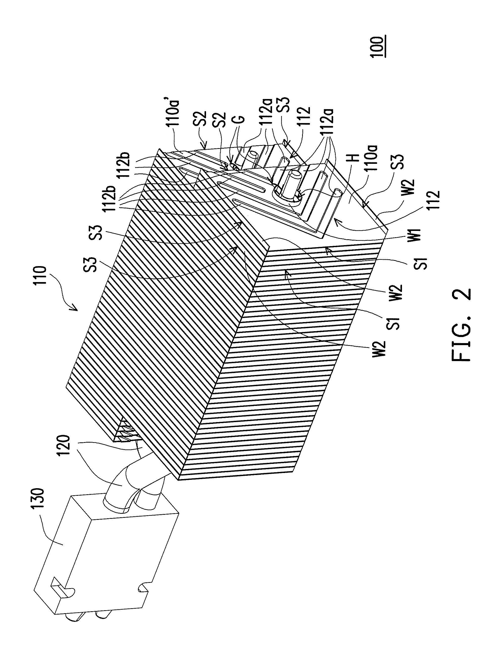
The invention provides a heat dissipating module with improved heat dissipation efficiency. This is achieved through the use of turbulent structures on the heat dissipation fins, which disrupt the boundary layer of the heat dissipation airflow and generate a vortex. This increases the heat convection efficiency and improves heat dissipation without increasing the rotation speed of the fan or the volume of the heat dissipation fin set. The invention is particularly useful for projection devices, which require high brightness, low noise, and small volume design trends.

Problems solved by technology

If the rotation speed of the fan is increased to correspondingly strengthen the heat dissipation airflow, noise would increase.
However, this increases the weight and volume of the projection device and significantly lowers the convenience and safety of the installation and the use of the projection device.

Method used


Image

  • Heat dissipating module having turbulent structures
  • Heat dissipating module having turbulent structures
  • Heat dissipating module having turbulent structures

Examples


Embodiment Construction

[0034]In the following detailed description of the preferred embodiments, reference is made to the accompanying drawings which form a part hereof, and in which are shown by way of illustration specific embodiments in which the invention may be practiced. In this regard, directional terminology, such as “top,”“bottom,”“front,”“back,” etc., is used with reference to the orientation of the Figure(s) being described. The components of the present invention can be positioned in a number of different orientations. As such, the directional terminology is used for purposes of illustration and is in no way limiting. On the other hand, the drawings are only schematic and the sizes of components may be exaggerated for clarity. It is to be understood that other embodiments may be utilized and structural changes may be made without departing from the scope of the present invention. Also, it is to be understood that the phraseology and terminology used herein are for the purpose of description an...


PUM


Abstract

A heat dissipation module includes a heat dissipation fin set. The heat dissipation fin set includes a plurality of heat dissipation fins, wherein these heat dissipation fins are stacked on each other, and each of the heat dissipation fins has a front side, a rear side opposite to the front side and at least one turbulent structure set. The turbulent structure set is located between the front side and the rear side and includes a plurality of first turbulent structures. The first turbulent structures are arranged from the front side to the rear side in sequence. A heat dissipation airflow flows from the front side toward the turbulent structure set along a flowing direction, and passes through the turbulent structure set to flow toward the rear side. An extending direction of each of the first turbulent structures is tilted relative to the flowing direction.

Description

CROSS-REFERENCE TO RELATED APPLICATION[0001]This application claims the priority benefit of Taiwan application serial no. 103144758, filed on Dec. 22, 2014. The entirety of the above-mentioned patent application is hereby incorporated by reference herein and made a part of this specification.BACKGROUND OF THE INVENTION[0002]1. Field of the Invention[0003]The invention relates to a heat dissipation module and a projection device having the heat dissipation module, and relates particularly to a heat dissipation module having turbulent structures and a projection device having the heat dissipation module.[0004]2. Description of Related Art[0005]A projection device is a display device used for producing large sized images. The principle of image formation of the projection device is converting an illumination light beam generated by a light source into an image light beam by a light valve, and then projecting the image light beam onto a projection screen or a wall through a projection l...

Claims


Application Information

Patent Timeline
Patent Type & Authority Applications(United States)
IPC IPC(8): F28D9/00F28F13/12
CPCF28F13/12F28D9/0093G03B21/16F28D15/0275F28F1/32
Inventor WANG, CHI-CHUANHUANG, PO-SHENGWU, SHANG-HSUANGLIN, TSUNG-CHINGCHUNG, WEN-YENCHEN, JHIH-HAO
Owner CORETRONIC
Why Eureka
Eureka Blog
Learn More