
GFCI self test software for autonomous monitoring and fail safe power denial

a self-testing, power denial technology, applied in the direction of electronic protection circuit testing, emergency protection arrangements for limiting excess voltage/current, instruments, etc., can solve the problems of gfci devices being susceptible to failure, devices not being able to properly detect ground faults and/or properly interrupt the flow of electrical current, and devices being unable to properly detect ground faults and/or electrical current. , to achieve the effect of preventing power loss and preventing power loss

Active Publication Date: 2016-06-23
HUBBELL INC
View PDF5 Cites 22 Cited by
  • Summary
  • Abstract
  • Description
  • Claims
  • Application Information

AI Technical Summary

Benefits of technology

The patent text describes a device called a GFCI that detects ground faults and works to prevent electrical shocks. A special circuit is used to monitor the functionality of the device without causing any false trips. This ensures that the device is always safe and reliable. The invention includes a filter capacitor that prevents the device from triggering an interrupter (a type of electrical switch) until a real fault occurs. This results in a safer and more reliable device that can protect against electrical shocks.

Problems solved by technology

Like most electro-mechanical devices, however, GFCI devices are susceptible to failure.
For example, one or more of the electronic components that drive the mechanical current interrupter device can short-out or otherwise become defective, as can components in the fault detector circuit or elsewhere within the device, rendering the device unable to properly detect the ground fault and / or properly interrupt the flow of electrical current.
A study performed by industry safety groups indicated that most often the public does not regularly test their GFCI devices for proper operation, i.e., by pressing the TEST button.
This study further revealed that some GFCI devices that had been in service for an extended period of time became non-functional and were unable to properly detect a fault condition, thus, rendering the device unsafe.
Specifically, it was discovered that after extended use GFCI devices fail to trip when a fault occurs, thus rendering the device operable as an electrical receptacle but unsafe in the presence of a fault condition.
Because the devices are not being regularly tested, this unsafe condition is exacerbated.
That is, people falsely believe the device is operational, in view of the fact that it adequately delivers power, when in fact the device is a potentially life-threatening hazard.
The discovery that GFCI devices deployed in the field are becoming increasingly non-operational and unsafe in combination with the realization that people do not regularly test their GFCI devices, regardless of manufacturer's explicit instructions to do so, initiated investigations into possible changes to the UL-943 standard to require the GFCI devices to self-test (e.g., auto-monitor) themselves without the need for human intervention.
The digital solutions offered thus far, however, are not ideal.
For example, several related art GFCI designs, including those directed at providing self-test functionality, suffer from nuisance tripping, a situation where the interrupter is actuated when neither a real ground fault, a manually generated simulated ground fault, nor an automatic self-test fault are present.
This unfavorable condition is believed by many to be worsened by the additional requirement of automatic self-testing, which results in additional inductive currents being generated within the device.

Method used


Image

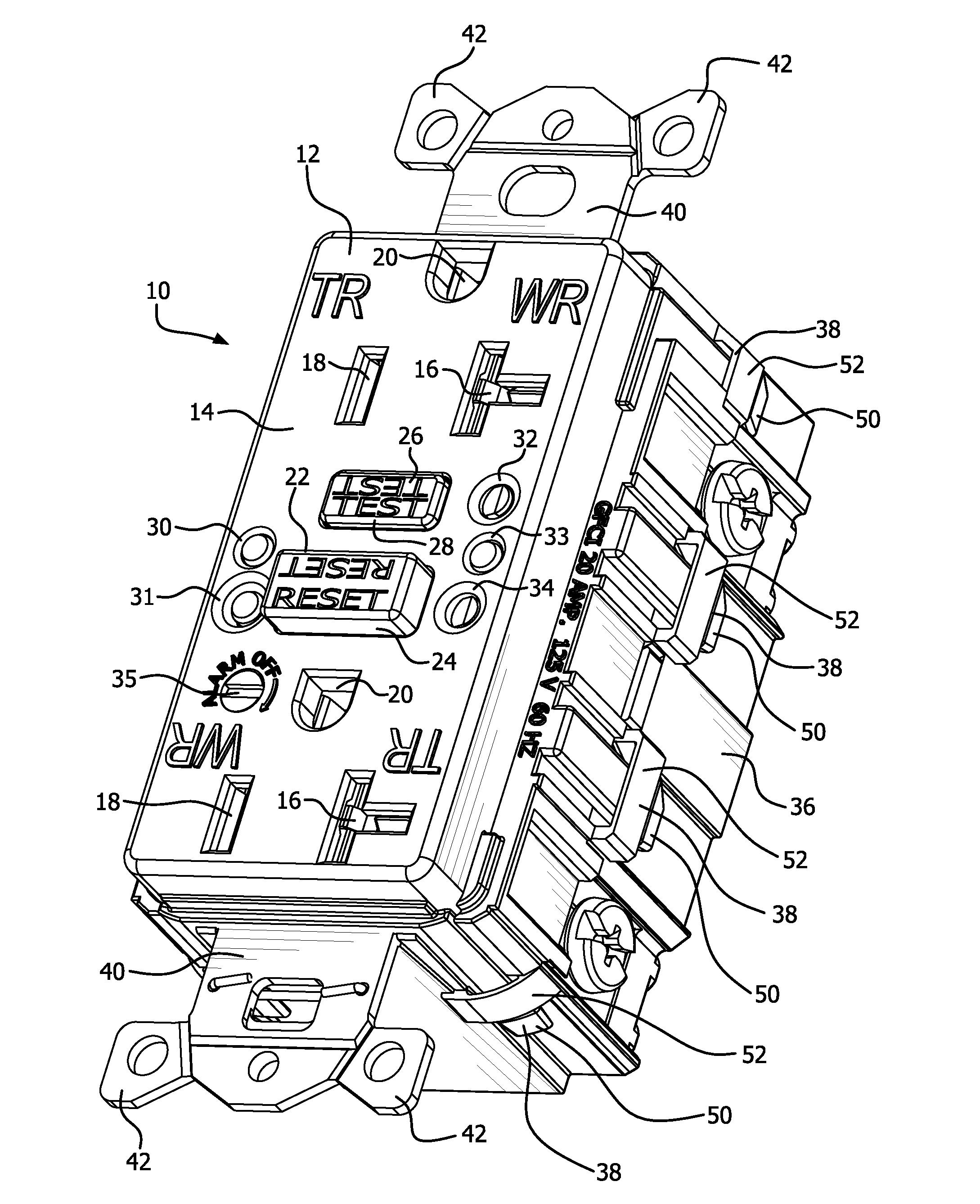
  • GFCI self test software for autonomous monitoring and fail safe power denial
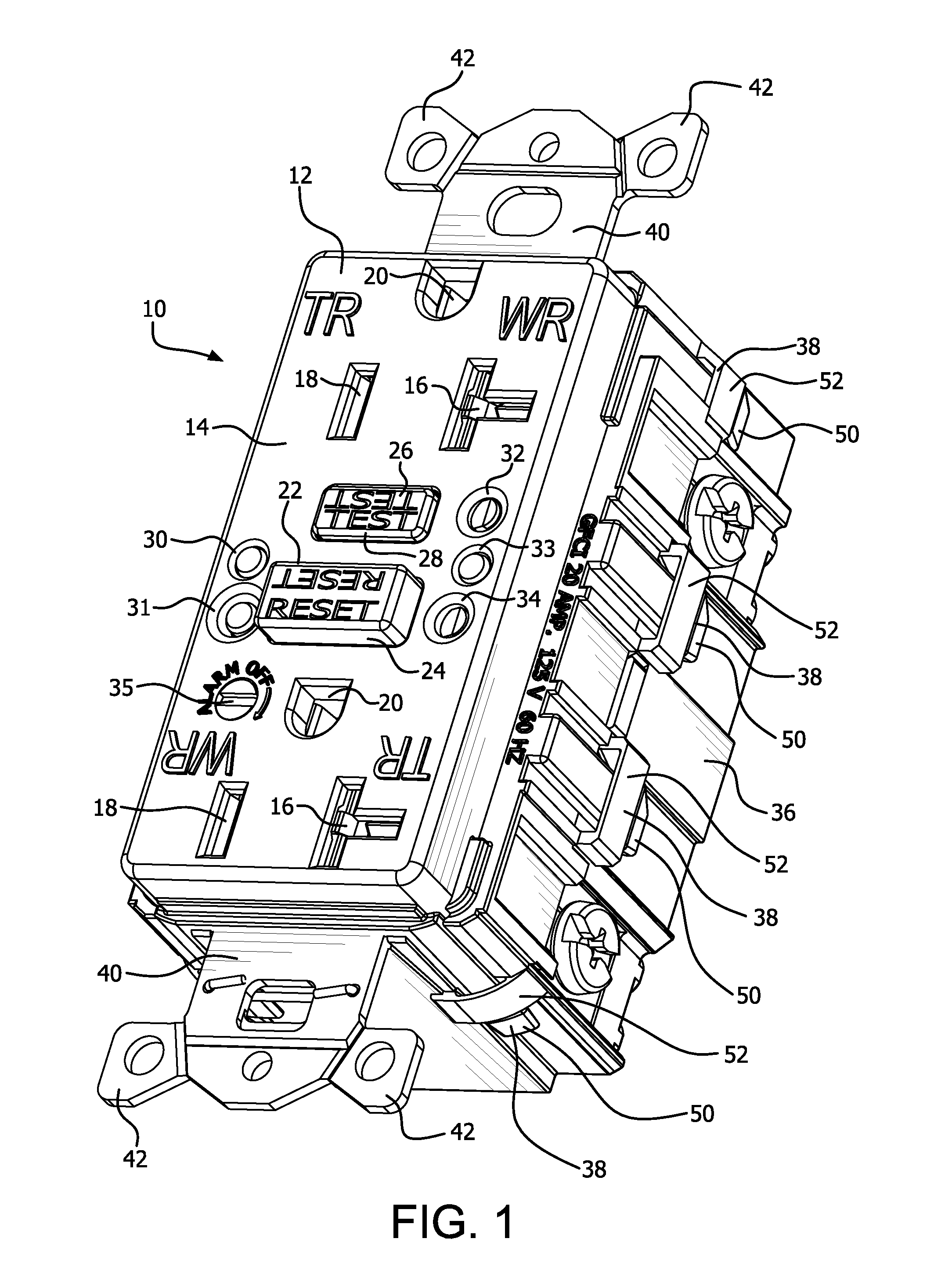
  • GFCI self test software for autonomous monitoring and fail safe power denial
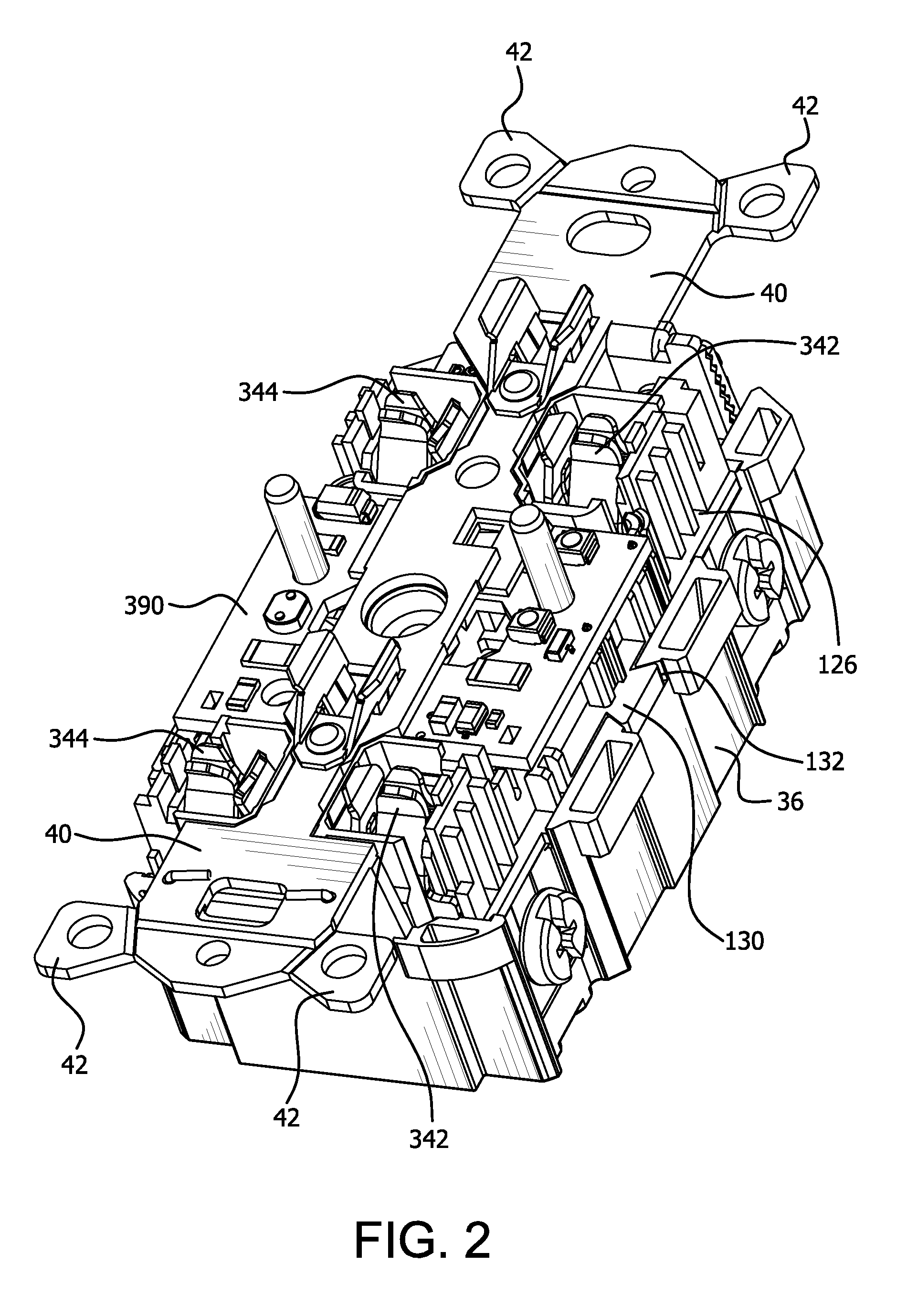
  • GFCI self test software for autonomous monitoring and fail safe power denial

Examples


Embodiment Construction

[0030]Before any embodiments of the invention are explained in detail, it is to be understood that the invention is not limited in its application to the details of construction and the arrangement of components set forth in the following description or illustrated in the following drawings. The invention is capable of other embodiments and of being practiced or of being carried out in various ways.

[0031]Exemplary embodiments of devices consistent with the present invention include one or more of the novel mechanical and / or electrical features described in detail below. For example, one or more The method and apparatus are particularly useful for carrying out image recognition or “fingerprinting” of a movable object, such as a person or a movable vehicle, and performing reacquisition of the movable object after a temporary loss of tracking, of the exemplary embodiments of the invention disclosed include auto-monitoring or, self-test, features. Some self-test features and capabilitie...


PUM


Abstract

A software code operates with a circuit interrupting device having an auto-monitoring circuit including a controller for automatically testing various functions and structures of the device. The auto-monitoring circuit initiates the software code which includes an auto-monitoring routine which, among other things, establishes a self-test fault during the positive or negative half-wave of an AC power cycle and determines whether the detection mechanisms within the device properly detect the self-test fault. Moreover, the software code executed by the controller compares sensed voltages from test signals with a determined or set maximum voltage value and compares the sensed voltages with a set or determined minimum voltage value. The sensed voltages must be greater than the maximum voltage value or lower than the minimum voltage value for a predetermined number of counts before an end-of-life state is determined for the circuit interrupting device. The number of counts reduces the likelihood of false detections of error conditions by the auto-monitoring circuit when determining whether the circuit interrupting device has reached the end of its useful life.

Description

CROSS-REFERENCE TO RELATED APPLICATIONS[0001]This application contains subject matter related to the subject matter contained in copending U.S. patent application Ser. No. 14 / 204,946, titled, “GFCI SELF TEST SOFTWARE FUNCTIONAL PROGRAM FOR AUTONOMOUS MONITORING AND FAIL SAFE POWER DENIAL OPERATIONS,” by Stephen P. Simonin, U.S. patent application Ser. No. ______ (Attorney Docket No. 208273-9005-US00), titled, “GFCI TEST MONITOR CIRCUIT,” by Stephen P. Simonin, and U.S. patent application Ser. No. ______(Attorney Docket No. 208273-9006-US00), titled, “GFCI SELF TEST LINE AND LOAD CONTACTS IMPROVED ALIGNMENT,” by Stephen P. Simonin, the entire contents of each of which are expressly incorporated herein by reference.FIELD OF THE INVENTION[0002]The present invention relates generally to switched electrical devices. More particularly, the present invention is directed to software code for operating a circuit interrupting device having an auto-monitoring circuit for automatically testing ...

Claims


Application Information

Patent Timeline
IPC IPC(8): G01R31/28G01R31/327H02H3/16G01R31/3187
CPCG01R31/2827H02H3/162G01R31/327G01R31/3187
Inventor SIMONIN, STEPHEN PAUL
Owner HUBBELL INC
Learn More