
Pentaband antenna

a technology of antennas and antennas, applied in the structure of radiating elements, elongated active elements, resonance antennas, etc., can solve the problems of relatively bulky surveillance systems, lack of adequate rf transmission and reception capabilities, and antennas that are somewhat fragile, etc., to achieve excellent transmission and reception capability.

Inactive Publication Date: 2016-06-23
XI3
View PDF4 Cites 5 Cited by
  • Summary
  • Abstract
  • Description
  • Claims
  • Application Information

AI Technical Summary

Benefits of technology

The invention is a device that forms an antenna element for RF signal reception and transmission. It has a single structure with a ground plane that supports an orthogonally opposed radiator element. The ground plane covers the circuit board to prevent interference and improves RF transmission and reception. The radiator element is designed for both horizontal and vertical polarized frequency reception and transmission. The technical effects of this invention include efficient RF signal reception and transmission with improved performance and reliability.

Problems solved by technology

However, the requirement to employ antennas with such broad capabilities results in surveying systems which are relatively bulky and do not provide adequate RF transmission and reception capabilities in all the desired frequencies and bandwidths due to interference and the like.
Conventional antennas employed for RF transmission and reception generally take the form of large cumbersome conic or Yagi type construction.
These antennas are somewhat fragile as they are formed by the combination of a plurality of parts including reflectors and receiving elements formed of light weight aluminum tubing or the like having various lengths to satisfy the frequency requirements of the received signals and plastic insulators.
However, in addition to being bulky and multiple in nature, these and many other prior art antennas fail to provide the high precision requirements of surveying and GPS systems, and are relative bulky.
There has not been a highly signal sensitive and easily constructed relatively small antenna for employment within a plurality of desired frequency bands.

Method used


Image

  • Pentaband antenna
  • Pentaband antenna
  • Pentaband antenna

Examples


Embodiment Construction

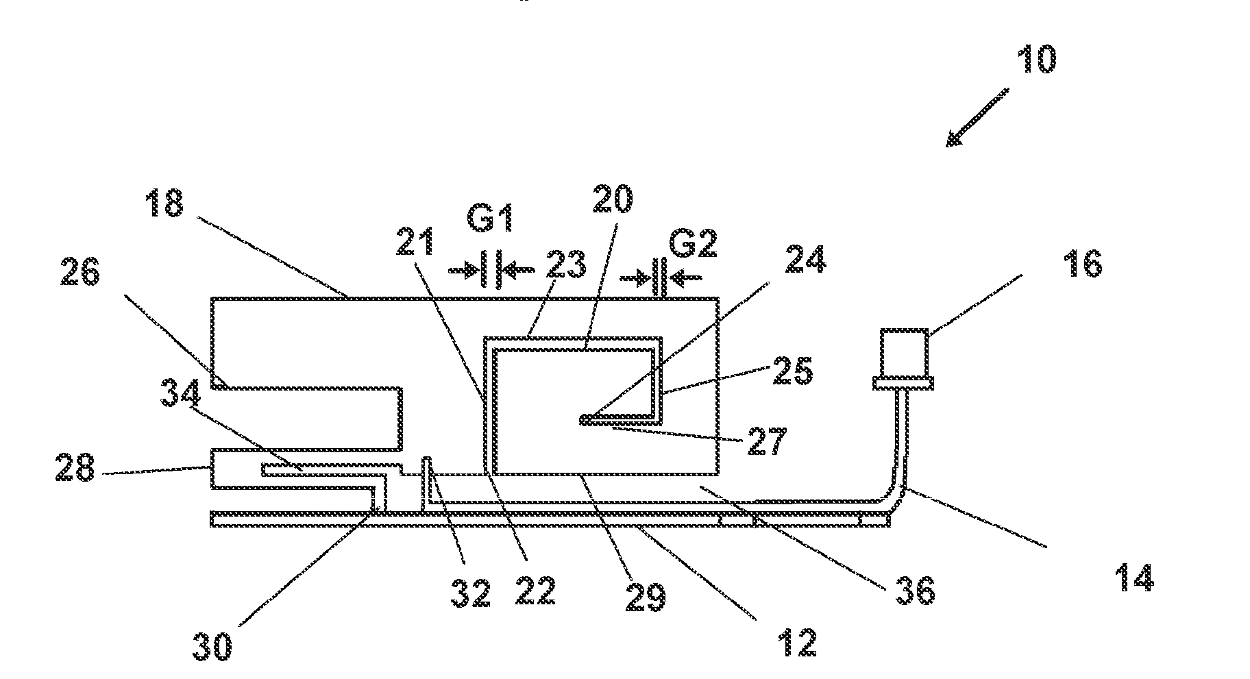
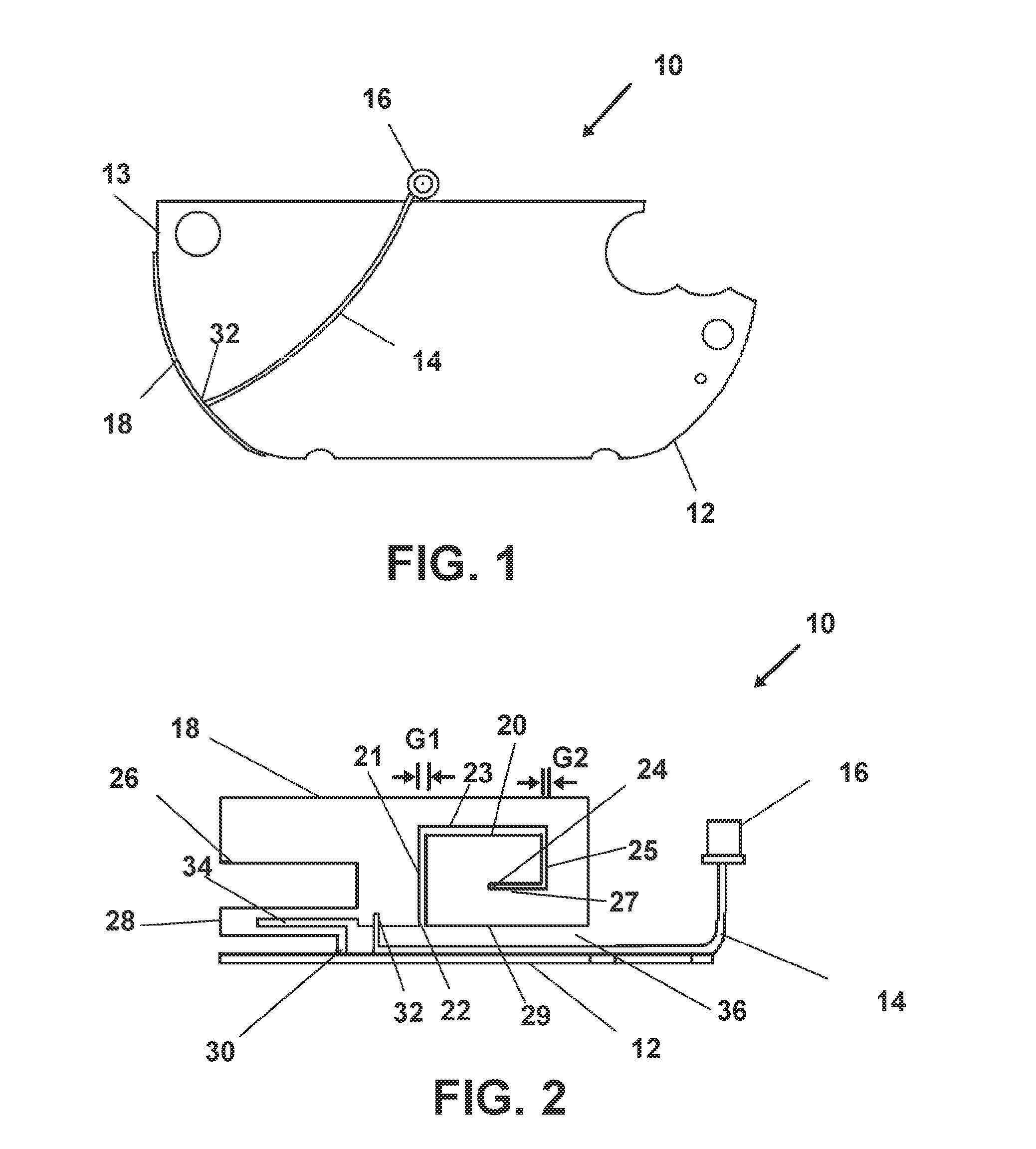
[0043]Now referring to drawings in FIGS. 1-13, wherein similar components are identified by like reference numerals, there is seen in FIG. 1 and FIG. 2 views of a particularly preferred mode of the antenna device 10 having a ground plane 12 and a first radiator element orthogonally opposed radiator element 18.

[0044]The device 10 is formed from a conductive material as for example, including but not limited to aluminum, copper, silver, gold, platinum or any other electrical conductive material which is suitable for the purpose intended. Further, in other preferred modes, the first radiator element 18 and ground plane 12 may be formed by coating a non-conductive substrate with the conductive material or more preferably by forming it from solid metal.

[0045]If formed from the non conductive substrate may be constructed of, for instance, either a rigid or flexible material such as, MYLAR, fiberglass, REXLITE, polystyrene, polyamide, TEFLON fiberglass, or any other dielectric material whi...


PUM


Abstract

An antenna element is disclosed which is formed in a unitary structure featuring a planar ground plane portion formed of electrically conductive material engaged with a perpendicular radiator element. One or a plurality of gaps formed into the radiator element provide one or a plurality of additional antenna elements which may be horizontally or vertically disposed for accommodating horizontally or vertically polarized RF transmission and reception.

Description

BACKGROUND OF THE INVENTION[0001]1. Field of the Invention[0002]This application claims priority to U.S. Provisional Patent Application Ser. No. 61 / 703083 filed on Sep. 19, 2012, and is incorporated herein in its entirety by this reference.[0003]The present invention relates to antennas for transmission and reception of radio frequency (RF) communications. More particularly the invention relates to an antenna element configured for RF communication across a plurality of bandwidths and in both horizontal and vertical polarization schemes. Due to the plurality of polarizations and frequencies, the antenna element is especially well adapted for employment with site surveying and positioning systems employing global navigation satellite systems for high accuracy site measurements.[0004]2. Prior Art[0005]Radio transmission and reception devices which use a plurality of frequencies and employ a plurality of RF polarization schemes, generally must employ a plurality of different antennas t...

Claims


Application Information

Patent Timeline
Patent Type & Authority Applications(United States)
IPC IPC(8): H01Q1/38H01Q9/04
CPCH01Q9/0414H01Q1/38H01Q1/24H01Q1/36H01Q9/40H01Q9/42H01Q5/371
Inventor COOPER, HENRYPENG, SHENG
Owner XI3
Learn More