Physical Therapy and Patient Movement System

a technology for physical therapy and patient movement, applied in physical therapy, medical science, nursing beds, etc., can solve the problems of immobility facing challenges, pain, discomfort, long-term limitations on mobility, etc., and achieve the effect of installing or dismantling very quickly

Inactive Publication Date: 2016-06-30
BROWNING JOHNNY C
View PDF17 Cites 10 Cited by
  • Summary
  • Abstract
  • Description
  • Claims
  • Application Information

AI Technical Summary

Benefits of technology

[0009]Another objective to provide an apparatus ...

Problems solved by technology

Without movement, atrophy of muscles and calcification of joints can set in and cause further pain, discomfort and long...

Method used


Image

  • Physical Therapy and Patient Movement System
  • Physical Therapy and Patient Movement System
  • Physical Therapy and Patient Movement System

Examples


first embodiment

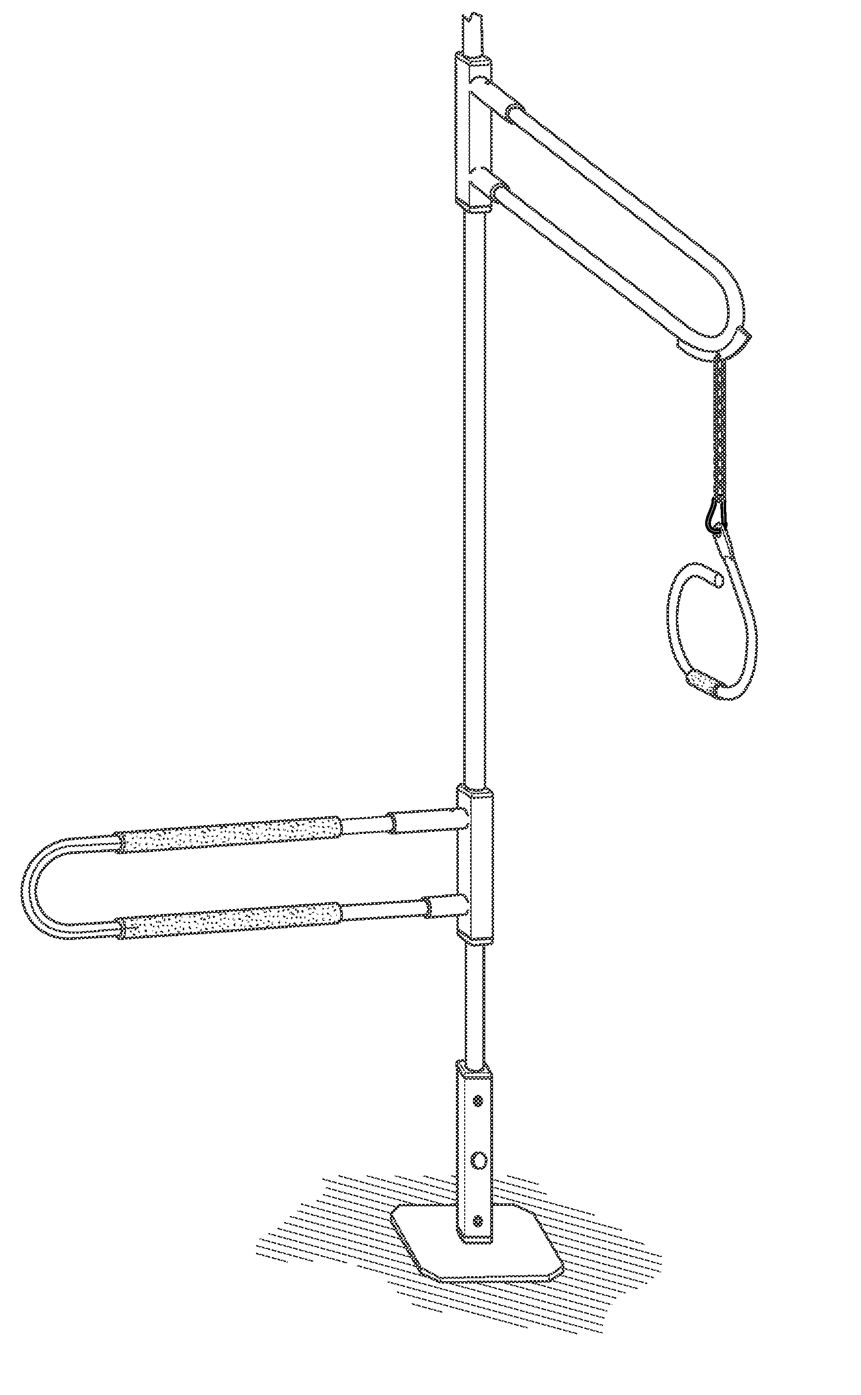
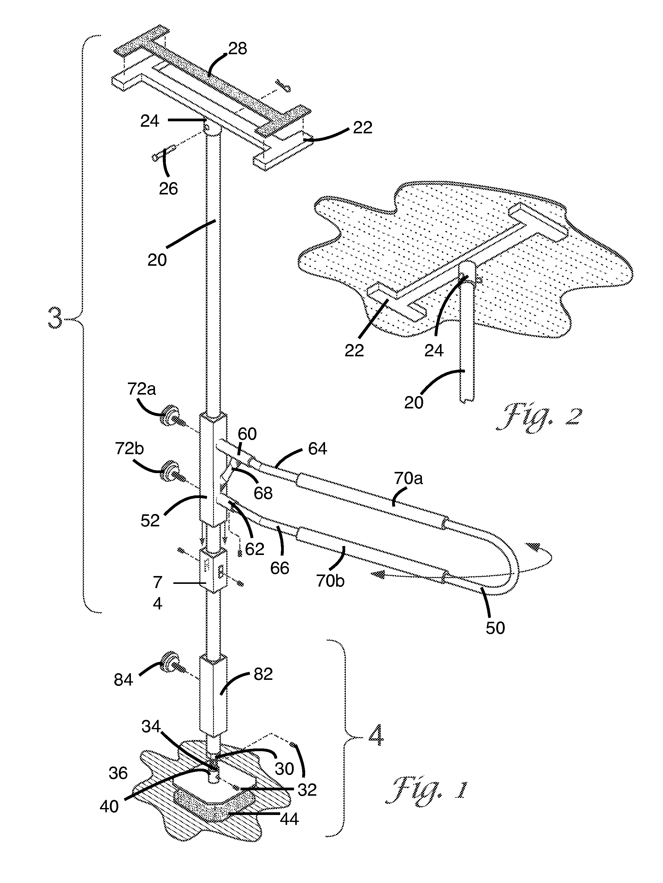
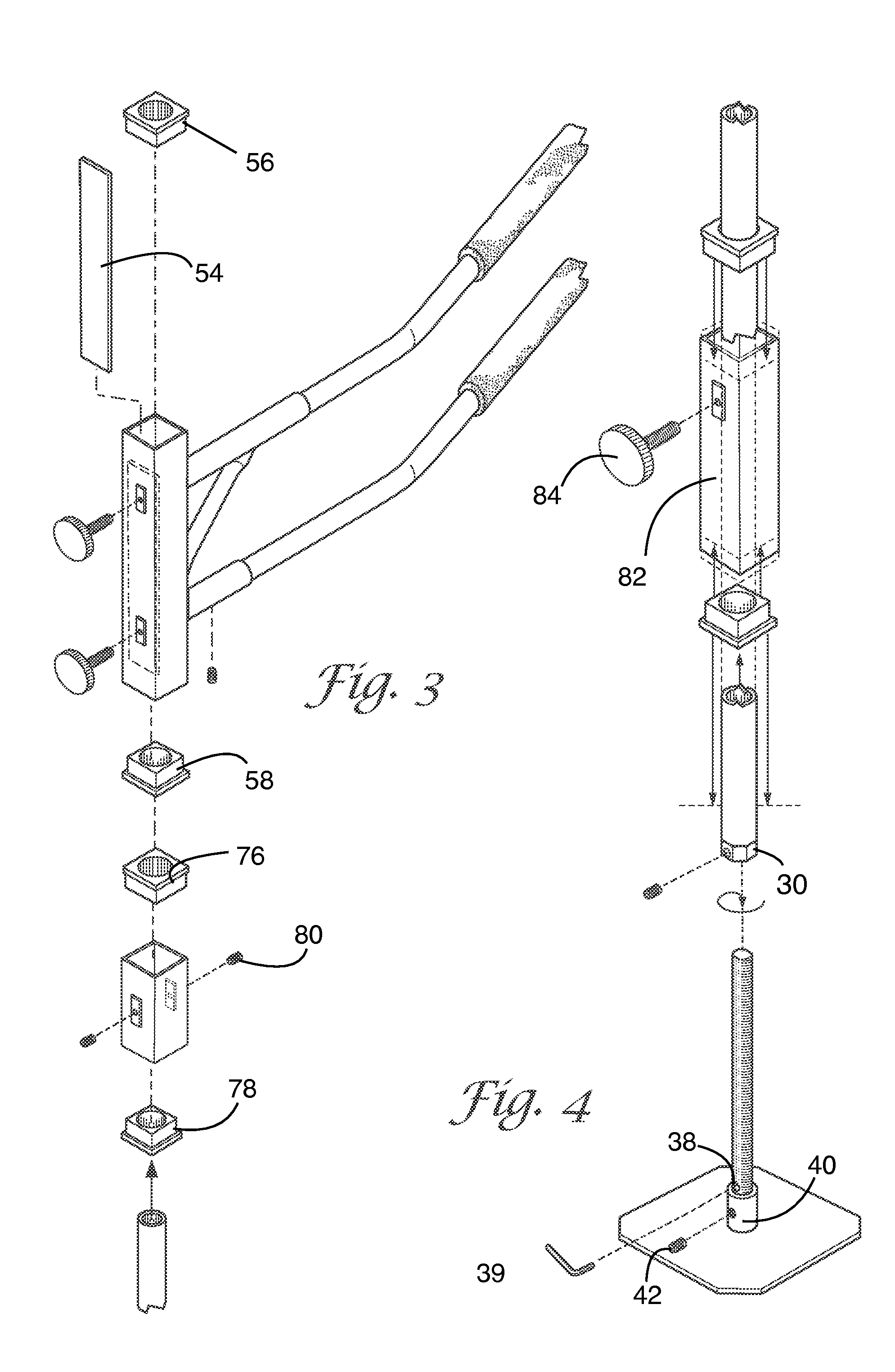
[0032]As in the first embodiment, the vertical pole 100 extends from floor to ceiling with a shaft 114 to provide tension and compression in mounting the device between the floor and ceiling. At the ceiling, the pole 100 is inserted into receiver tube 104 located on the ceiling plate 102 and secured with clevis pin 106. Meanwhile, a threaded receiver 110 is pre-welded onto a floor plate 116 and receives an opposite end of the vertical support pole 100 (floor end) via a shaft 114. Two set screws 112 are located on a side of the threaded receiver to prevent the support pole 100 from rotating when a handle 120 or 130 is in use.

second embodiment

[0033]The first device in the second embodiment has two opposing receiver tubes 122a, 122b connected (welded) horizontally and perpendicular to the square tube main head 124. The square tube main head 124 has two (one on each end) square-to-round reducing bushings 126 and 128 (UHMW) allowing the square head 124 to fit onto the round floor to ceiling pole 100. The square head 124 is now positioned at a desired height and secured by tightening the four cone tip set screws 130. The square head 124 has a grab bar 132 connecting the two opposing upper receiver tubes 122a and 122b, thus creating a continuous grab bar 132 horizontal and perpendicular to the pole 100. A gusset brace 134 connects to the bottom of the grab bar 132 and connects to the square head 124. The upper receiver tubes 122a are longer than lower receiver tubes 122b allowing much easier insertion of the 180 degree hand rails, such as grab bar 132.

[0034]In a second device of the second embodiment, angularly opposed hand r...


PUM


Abstract

A physical therapy and physical assist apparatus and system includes a vertical support pole with mount for ceiling and floor. A shaft in combination with the pole is used to adjust the height of the pole to fit the distance between ceiling and floor and mount the apparatus. At least one handle is attached to the vertical pole and via a rotating head and brake assembly. The brake assembly includes a brake pad for adjustment of resistance on a walk-around arrangement thereof. The handle includes a 25 degree kick out in the walk-around arrangement of the apparatus.

Description

PRIORITY CLAIM[0001]The present application claims benefit of United States provisional patent application No. 62 / 083,898 filed by applicant, Johnny C. Browning, on Nov. 25, 2014.FIELD OF THE INVENTION[0002]The present invention relates to physical therapy and patient movement systems, and more particularly pertains to a medical walk-around device for enabling patients and immobile individuals to perform physical therapy at home.BACKGROUND OF THE INVENTION[0003]Individuals recovering from a stroke, a broken hip or limb or other debilitating disease or condition require physical assistance and physical therapy to regain mobility and maintain strength. Without movement, atrophy of muscles and calcification of joints can set in and cause further pain, discomfort and long-term limitations on mobility. Those who are immobile face challenges in the simple tasks rising and moving between two points. The present invention helps to overcome these problems by providing a system that enables b...

Claims


Application Information

Patent Timeline
IPC IPC(8): A61H3/00A63B21/015
CPCA63B21/015A61H3/00A63B21/1681A63B23/047A63B2208/0204A63B2225/093A63B21/00069A63B21/4035A63B21/4049A63B2022/0094A61G7/053A61G7/1038A61G7/1044A63B71/0009A63B71/023A63B2071/0018A63B2071/0063A63B2071/026A63B21/068A63B69/0057A63B21/012A63B21/00181
Inventor BROWNING, JOHNNY C.
Owner BROWNING JOHNNY C
Why Eureka
Try Eureka