Friction coupling

Inactive Publication Date: 2016-06-30
AB SKF
View PDF0 Cites 0 Cited by
  • Summary
  • Abstract
  • Description
  • Claims
  • Application Information

AI Technical Summary

Benefits of technology

[0015]The invention is based on the understanding that a critical pressure exists at which the friction coefficient between the friction surface and the counterface ceases to be governed by the high abrasive friction coefficient. When the critical pressure is exceeded, adhesive friction becomes the dominant friction mechanism, which has a lower friction coefficient than abrasive friction. The present inventors have developed a model for determining the critical pressure in a friction coupling of the kind defined above. The model is used to determine the asperity density at which the critical pressure is reached. If the predefined pressure P in a given application is assumed to equal the critical pressure, then the corresponding asperity density is the minimum thre

Problems solved by technology

A disadvantage of using diamond grains in the friction-enha

Method used


Image

  • Friction coupling
  • Friction coupling
  • Friction coupling

Examples


Example

EXAMPLE

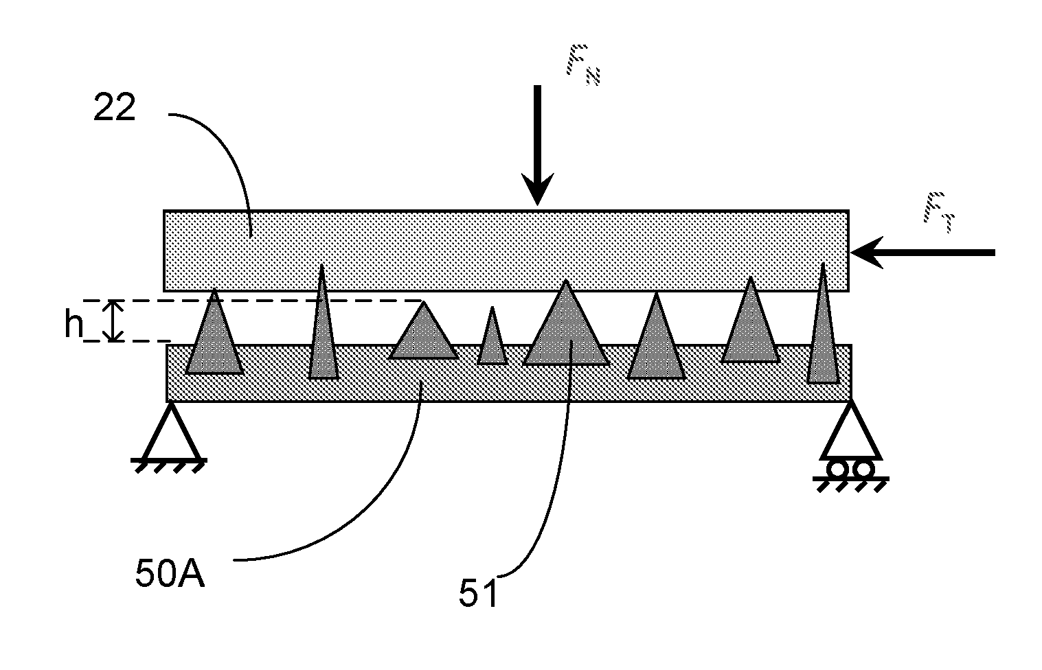
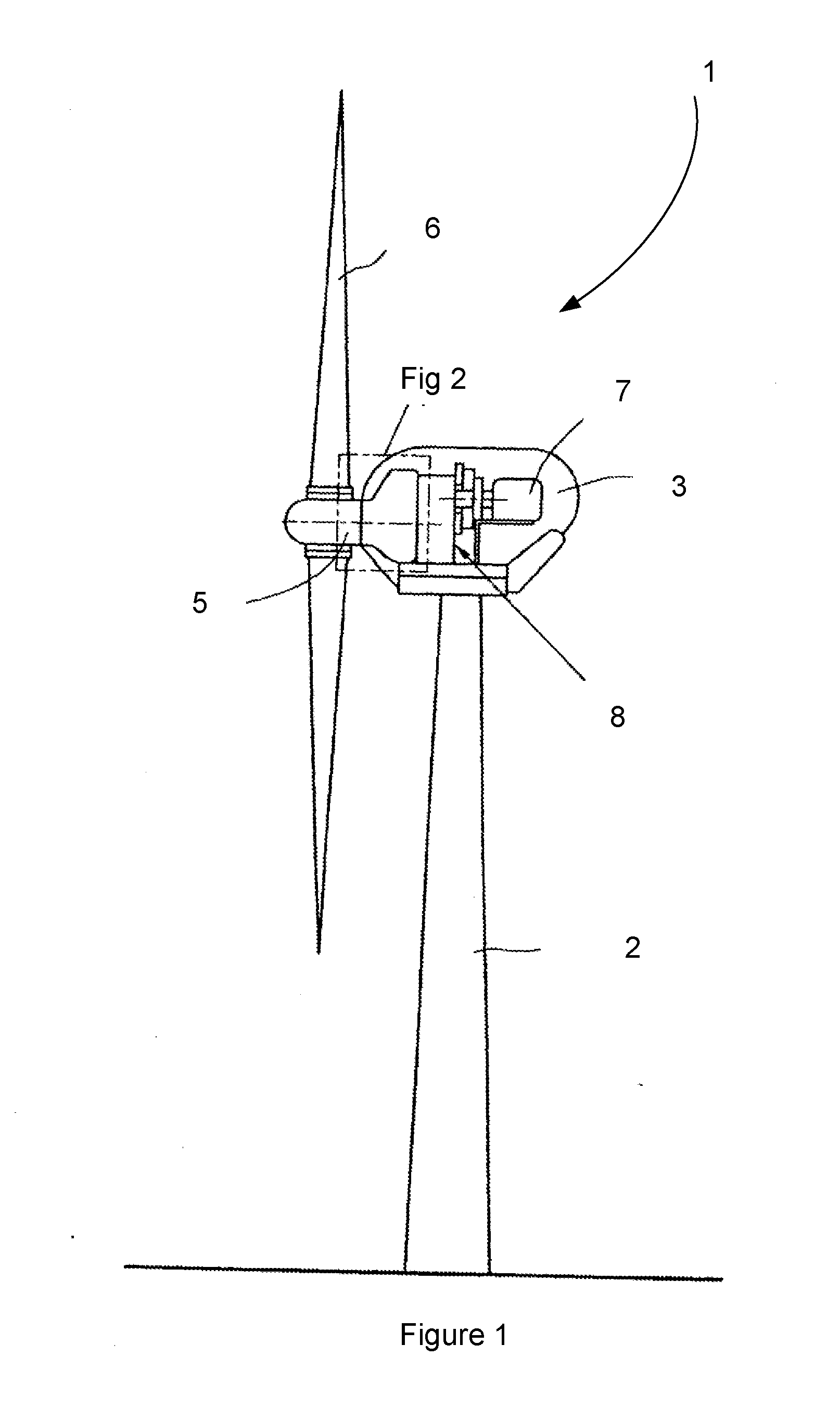
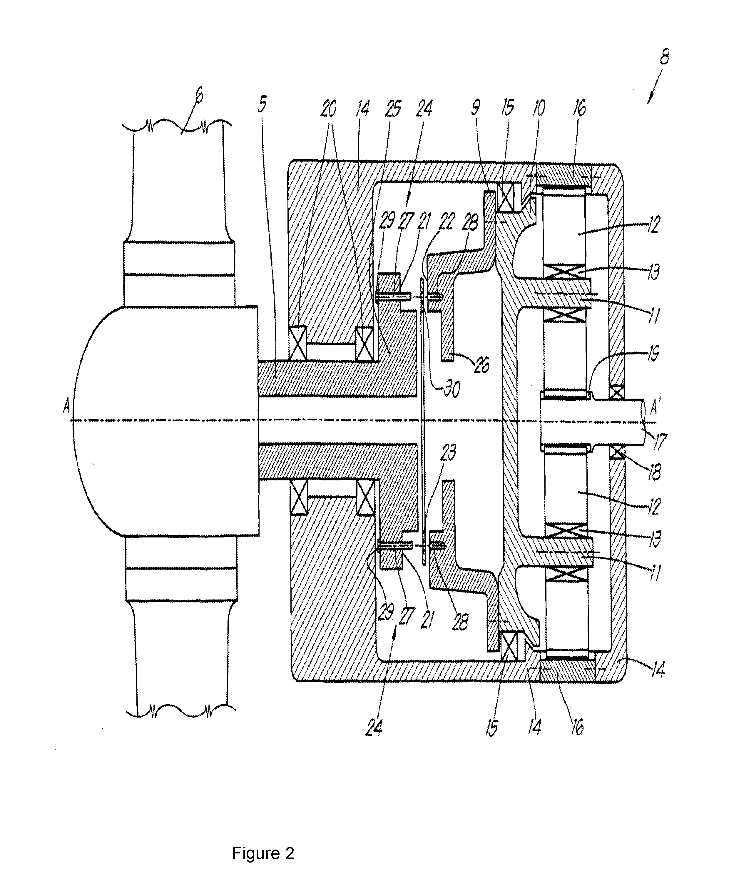
[0070]A commercially available friction coupling of the kind described with reference to FIGS. 1 and 2 was examined. The friction surface of the friction disk 23 consisted of diamond particles in a Nickel bond later. The asperity density and mean asperity height of the friction surface were measured by scanning a region of the friction surface using a laser scanning microscope. The measured asperity density was 313 asperities per mm2 and the measured mean asperity height was 21.7 μm. The measured standard deviation was 9 μm.

[0071]The material of the counterface was cast iron. The coefficient of friction between the friction surface and the counterface was measured using a conventional test method as described in ASTM D1894. A value of 0.75 was measured. The frictional force measured during the test is representative of the total friction, which consists of abrasive friction and adhesive friction. The abrasive friction is due to the hard asperities which plough through the cou...


PUM


Abstract

A friction coupling comprising first and second coupling surfaces. A friction surface is provided on the first coupling surface and a counterface is provided on the second coupling surface. The friction coupling further comprises preload elements, such as bolts, for applying a predefined pressure on the first and second coupling surfaces. The friction surface of the coupling comprises abrasive particles that constitute hard asperities which protrude from a substrate of the friction surface with a height h. The abrasive particles are provided on the substrate in a predefined asperity density η. The predefined asperity density η is greater than a minimum threshold for the asperity density ηmin and is less than 2.5*ηmin. The minimum threshold is defined by the following relationship:
ηmin=π4PHμabr2h_2+σ2
    • where
    • η asperities per unit (surface area) (m−2);
    • P pressure (Pa);
    • μabr coefficient of friction;
    • H hardness (counterface) (Pa)
    • h height (asperities) (m);
    • σ standard deviation (asperity heights) (m).

Description

CROSS REFERENCE TO RELATED APPLICATION[0001]This is a United States National Stage Application claiming the benefit of International Application Number PCT / EP2013 / 068809 filed on 11 Sep. 2013 (11.09.2013), which is incorporated herein by reference in its entirety.FIELD OF THE INVENTION[0002]The present invention relates to the field of torque-transfer couplings based on the principle of friction between materials. More particularly, the invention is directed to a friction coupling comprising a friction surface that is provided with embedded abrasive particles. The invention is further directed to a method of determining whether a friction coupling will provide sufficient friction torque under specific application conditions.BACKGROUND TO THE INVENTION[0003]A friction coupling of the above kind is disclosed in EP 2075466. The coupling concerns a connection between a low speed main shaft of a wind turbine and an input shaft of a transmission gearbox. The main shaft and input shaft hav...

Claims


Application Information

Patent Timeline
IPC IPC(8): F16D7/02G01N19/02G01N3/44
CPCF16D7/025G01N19/02G01N3/44F16D1/033
Inventor KADIN, YURIHAN, BO
Owner AB SKF
Why Eureka
Try Eureka