Improvements in and relating to visors

Active Publication Date: 2016-06-30
BAE SYSTEMS PLC
View PDF2 Cites 14 Cited by
  • Summary
  • Abstract
  • Description
  • Claims
  • Application Information

AI Technical Summary

Benefits of technology

[0028]The display visor is preferably positioned, or deployable to a position, between the body of the helmet and the glare visor. The optical coating may be formed upon the surface of the glare visor facing away from the body of the helmet. Consequently, light from the HMD which has transmitted through the display visor may subsequently reflect from the optical coating formed on the glare visor in a direction back towards the wearer of the helmet. This may result in the formation of a perceivable second image, or “ghost” image, of the projected HMD display light which is misaligned with the primary HMD image reflected by the display visor (closer to the wearer). The misalignment is a consequence of the typically offset positioning of a HMD display projector requiring oblique reflection of HMD light to the wearer's eyes via the display visor. Secondary reflection from a surface behind the display visor (i.e. the glare visor) results in a lateral off-set in the secondary image relative to the primary HMD image. However, by placing the optical coating on a surface of the glare visor furthest from the display visor, the secondary reflected HMD light is doubly attenuated by a double-pass through the material of the glare visor thereby reducing the brightness of the secondary image and improving t

Problems solved by technology

However, this comes at the cost of greater HUD power consumption and reduced equipment lifetime.
Furthermore, the brightness of both the HUD image and the HMD image are constrained by many fac

Method used


Image

  • Improvements in and relating to visors
  • Improvements in and relating to visors
  • Improvements in and relating to visors

Examples


Example

[0048]In the drawings like reference symbols refer to like items.

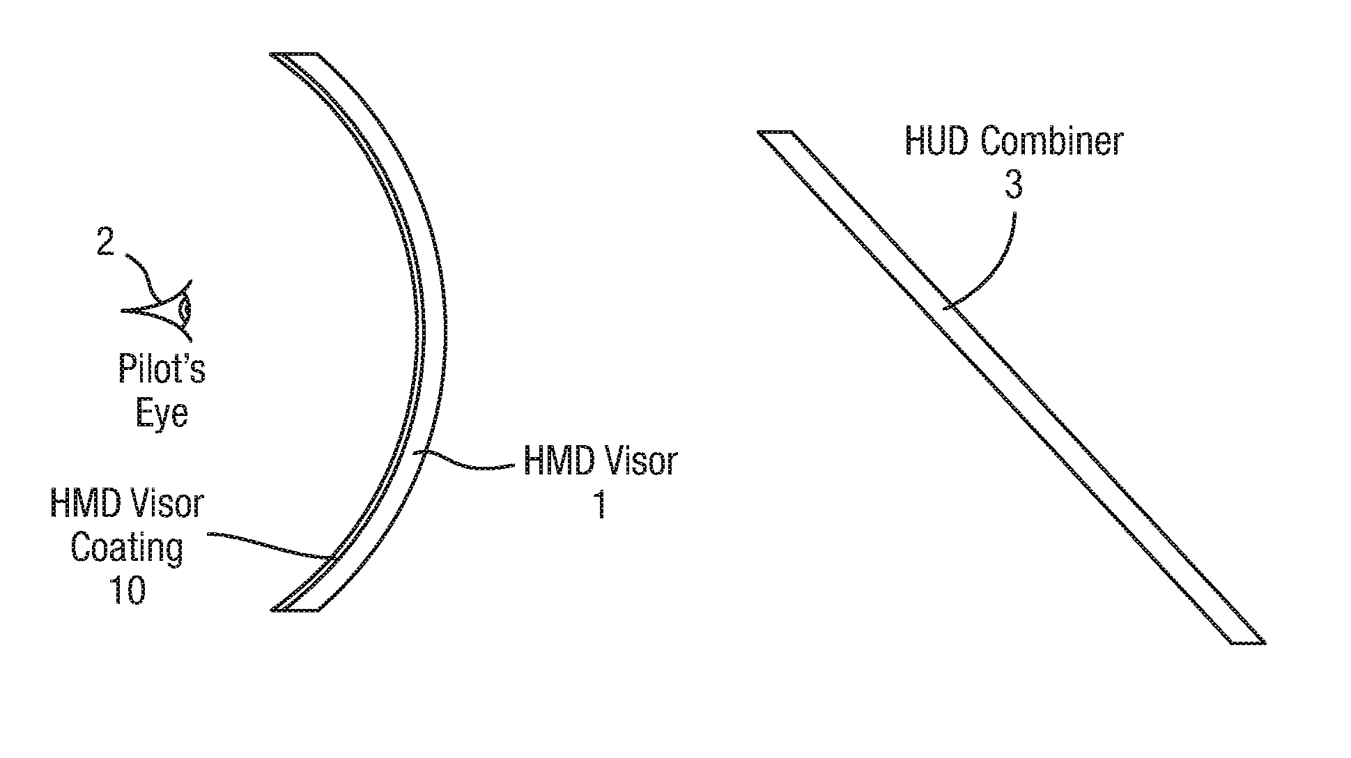
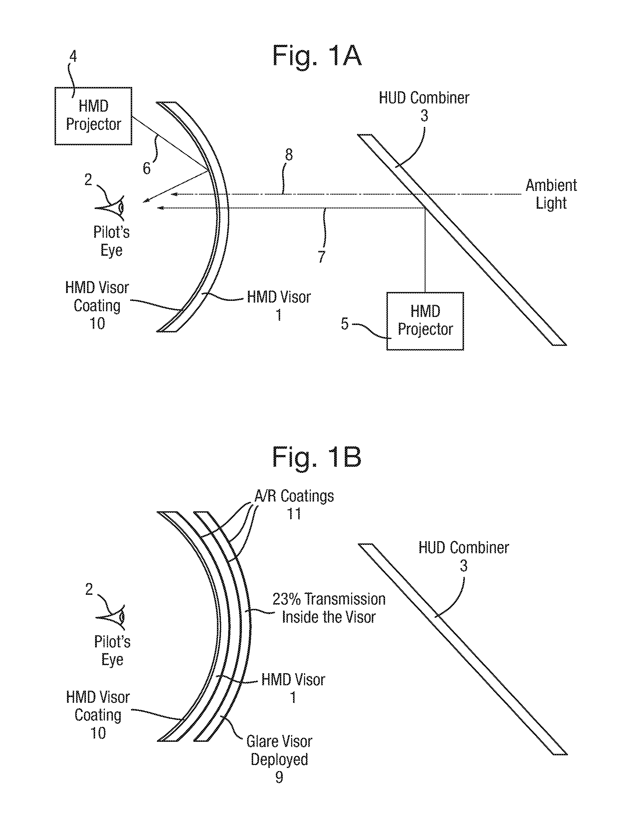
[0049]FIG. 1A schematically shows a HMD display visor 1 of an aviator's helmet containing / carrying a helmet-mounted display (HMD) projector 4 (helmet not shown, for clarity) in relation to the wear's eye(s) 2, in combination with a head-up (HUD) display combiner 3 of a HUD display unit 5. FIG. 1B shows the arrangement of FIG. 1A with the addition of a glare visor 9 deployed over the HMD display visor to reduce the perceived glare of ambient light to comfortable levels.

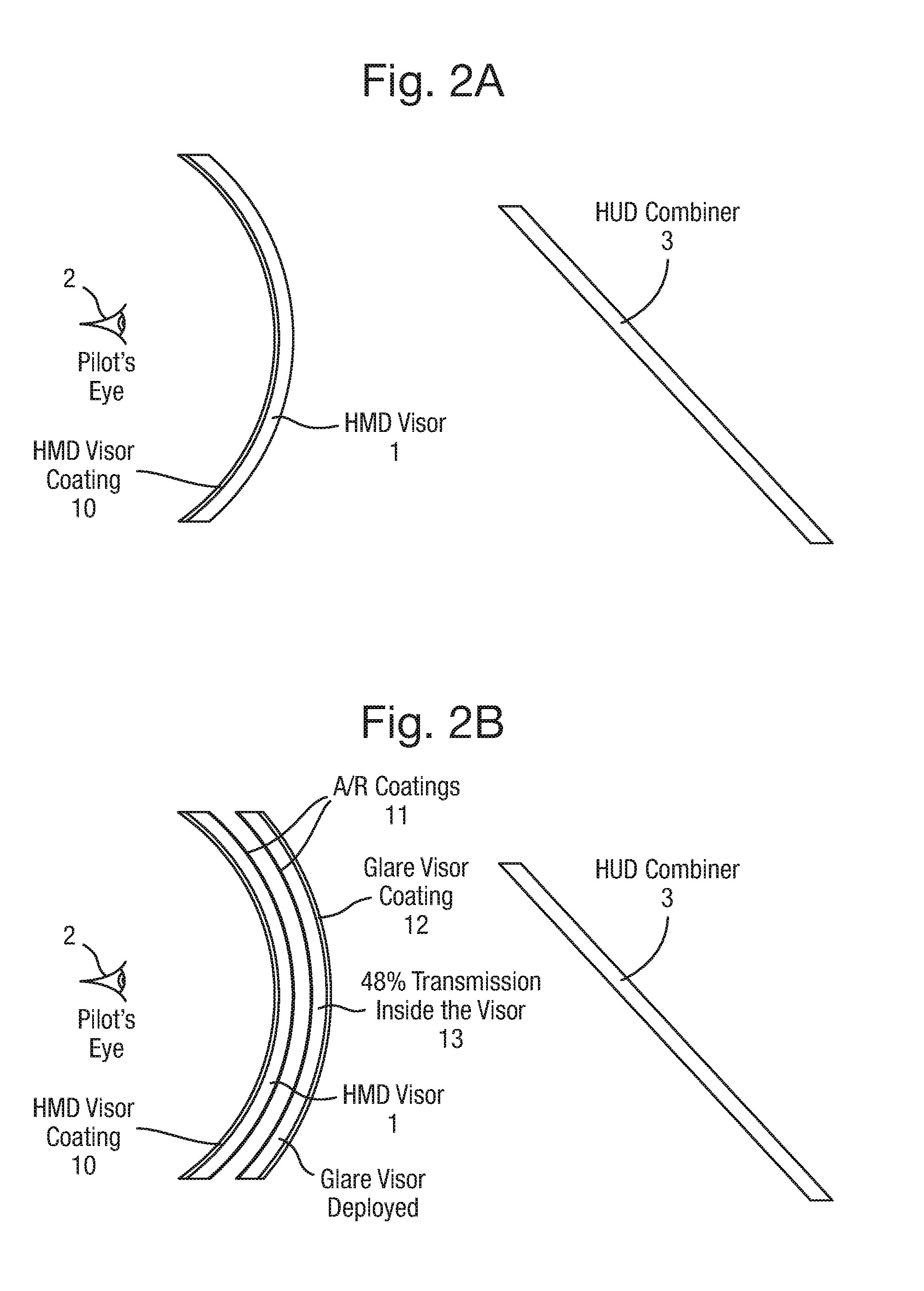
[0050]The HMD display visor has a visor coating 10 on its wearer-facing surface comprising an optical coating (e.g. multi-layer) designed to be preferentially reflective at a narrow band of optical wavelengths centred upon the wavelength of the projected light 6 (e.g. 530 nm) produced by the HMD projector for the HMD projected imagery. The outward-facing surface of the HMD display visor 1 and each surface of the glare visor 9 (FIG. 1B) bears an anti-refle...


PUM


Abstract

A glare visor (13) for reducing ambient light intensity perceived by a wearer viewing a head-up display (3) employing display light (7) including a given wavelength(s) of light. The visor includes a visor body comprising optically transparent material which is partially absorbing of light of visible optical wavelengths thereby to reduce the intensity of ambient light transmitted therethrough to the wearer. A transparent optical coating (12) is formed upon a surface of the visor body which is partially transmissive of light of visible optical wavelengths amongst which it is preferentially transmissive of light of a sub-range of wavelengths for including therein the wavelength(s) of display light. This permits a perceived enhancement of contrast between display light (7) relative to ambient light (8).

Description

FIELD OF THE INVENTION[0001]The invention relates to visors. In particular, though not exclusively, the invention is suitable for use with a Head-Up display (HUD) or the like, such as are commonly used in aircraft and other vehicles, and may be additionally suitable for use with / on a helmet (such as an aviator's helmet) in conjunction with both a HUD and a Helmet-Mounted Display (HMD).BACKGROUND[0002]Both Helmet Mounted Displays (HMD) and Head-Up Displays (HUD) typically use green light to display imagery. An aircrew helmet may have two visors; a HMD display visor which is a clear visor onto which the HMD projection apparatus projects an image; and a glare visor for providing a reduction in ambient brightness. The latter is deployed when the outside world is too bright for comfortable viewing.[0003]When the two visors are used together the HMD display visor suppresses the brightness of the HUD display light as perceived by the helmet wearer. This occurs because HMDs display visors s...

Claims


Application Information

Patent Timeline
IPC IPC(8): G02B27/01G02B5/20G02B5/22A42B3/22
CPCG02B27/0172A42B3/226G02B2027/0118G02B5/223G02B5/205A42B3/042A42B3/228G02B5/22
Inventor MILLS, COLIN RICHARDMARSHALL, IAN
Owner BAE SYSTEMS PLC
Why Eureka
Try Eureka