Intelligent equipment sequencing

a technology of intelligent equipment and equipment sequencing, applied in the direction of data switching network, heating types, static/dynamic balance measurement, etc., can solve the problems of direct affecting the energy usage of individual equipment pieces, the “stage and forget” process may be problematic, and the laborious on the part of the operator, so as to improve or optimize the overall energy efficiency

Active Publication Date: 2016-06-30
OPTIMUM ENERGY
View PDF13 Cites 23 Cited by
  • Summary
  • Abstract
  • Description
  • Claims
  • Application Information

AI Technical Summary

Benefits of technology

[0015]The present invention is generally directed toward systems and methods for sequencing HVAC equipment of an HVAC system using data recorded in situ to build a model capable of making predictions about equipment efficiency and using that information, in combination with predictions about building load, to produce an operational sequence for the HVAC equipment that promotes an improved or optimized overall energy efficiency for the HVAC system.
[0016]In addition, this data, prediction and modeling can be used to determine which pieces of HVAC equipment work more efficiently with other pieces of HVAC equipment, taking into account the covariance between the different pieces of HVAC equipment, producing further sequencing that will operate the HVAC equipment together in efficient covariance combinations, that promotes an improved or optimized overall energy efficiency for the HVAC system.
[0017]In addition, this data, prediction and modeling can be used to optimize when best to stage additional HVAC equipment on or off, based on the future load prediction of the HVAC equipment, which promotes an improved or an optimized overall energy efficiency for the HVAC system.
[0018]In addition, this data, prediction and modeling can be used to determine at which loads the HVAC equipment operates at its best efficiency, allowing for the load balancing of the different similar pieces of operating HVAC equipment, to keep them operating in their ‘Sweet Spot’, for example if one chiller operates most efficiently at a load of 500 tons, it can be load balanced via water flow, valves or control set points, to remain operating at that “sweet spot” of 500 tons in parallel with another operating chiller which operates efficiently at 700 tons, also load balanced to operate producing 700 tons via water flow, valves or control set points, to remain operating at that “sweet spot”, which promotes an improved or optimized overall energy efficiency for the HVAC system.
[0019]In one embodiment, the process is automated and utilizes Bayesian computational models or algorithms to generate an initial sequence. The process reduces engineering hours and may advantageously provide a means to predict potential sequencing problems for similar types of HVAC equipment.

Problems solved by technology

Many of the conventional sequencing methods involve many hours of labor on the part of a knowledgeable engineer and the sequence modeling typically occurs only at the outset when the equipment is initially commissioned.
The “stage and forget” process may be problematic since equipment energy efficiencies can drift over time as parts or components wear, critical operating fluids leak or are used up, and / or conditions change in the system as a whole.
Such operational changes directly affect the energy usage of individual pieces of equipment.
The reasons that equipment like chillers, pumps, fans, cooling towers or boilers may have different efficiencies may be due to (1) manufacturing differences (large or small); (2) poor equipment (3) equipment wear or broken parts; (4) contamination or loss of refrigerant within a chiller; and / or (5) fouling or buildup of material on working surfaces.
Additionally, while the manual sequencing process may capture trends in equipment efficiency it is often unable to observe small fluctuations in efficiency.
Since manufacturer specifications are often used in the manual sequencing process it can also be difficult to perceive differences in equipment energy efficiencies for the same model.
This may result in operating less efficient equipment, using excess energy that may be “left on the table.”
When equipment is left inoperable for long periods of time, the equipment may decay or lose critical operating fluids to leakage or evaporation.
Over time, the energy efficiencies of the equipment may drift as shown in FIG. 2, and such drifts may be result in a reduced or poorer energy efficiency for that particular equipment.

Method used


Image

  • Intelligent equipment sequencing
  • Intelligent equipment sequencing
  • Intelligent equipment sequencing

Examples


Embodiment Construction

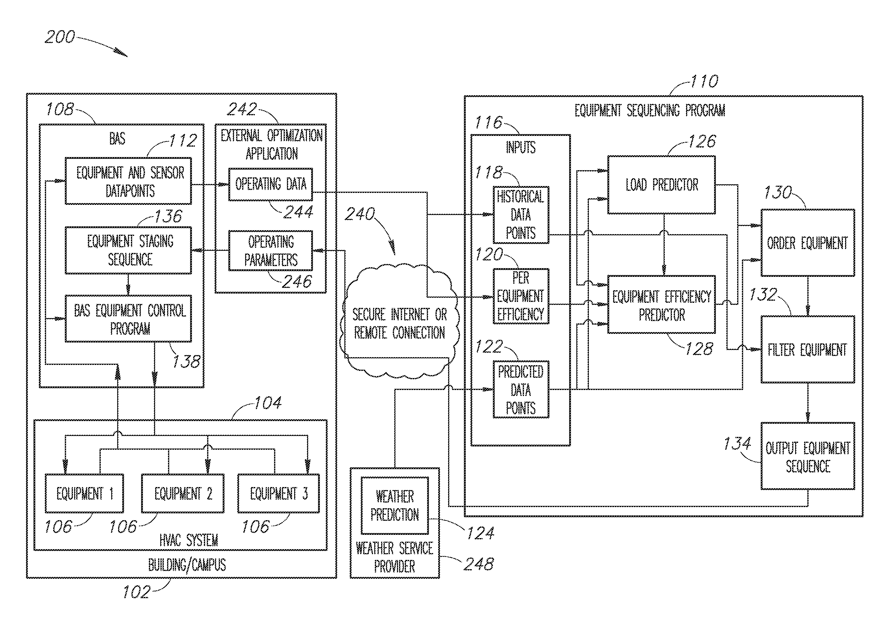
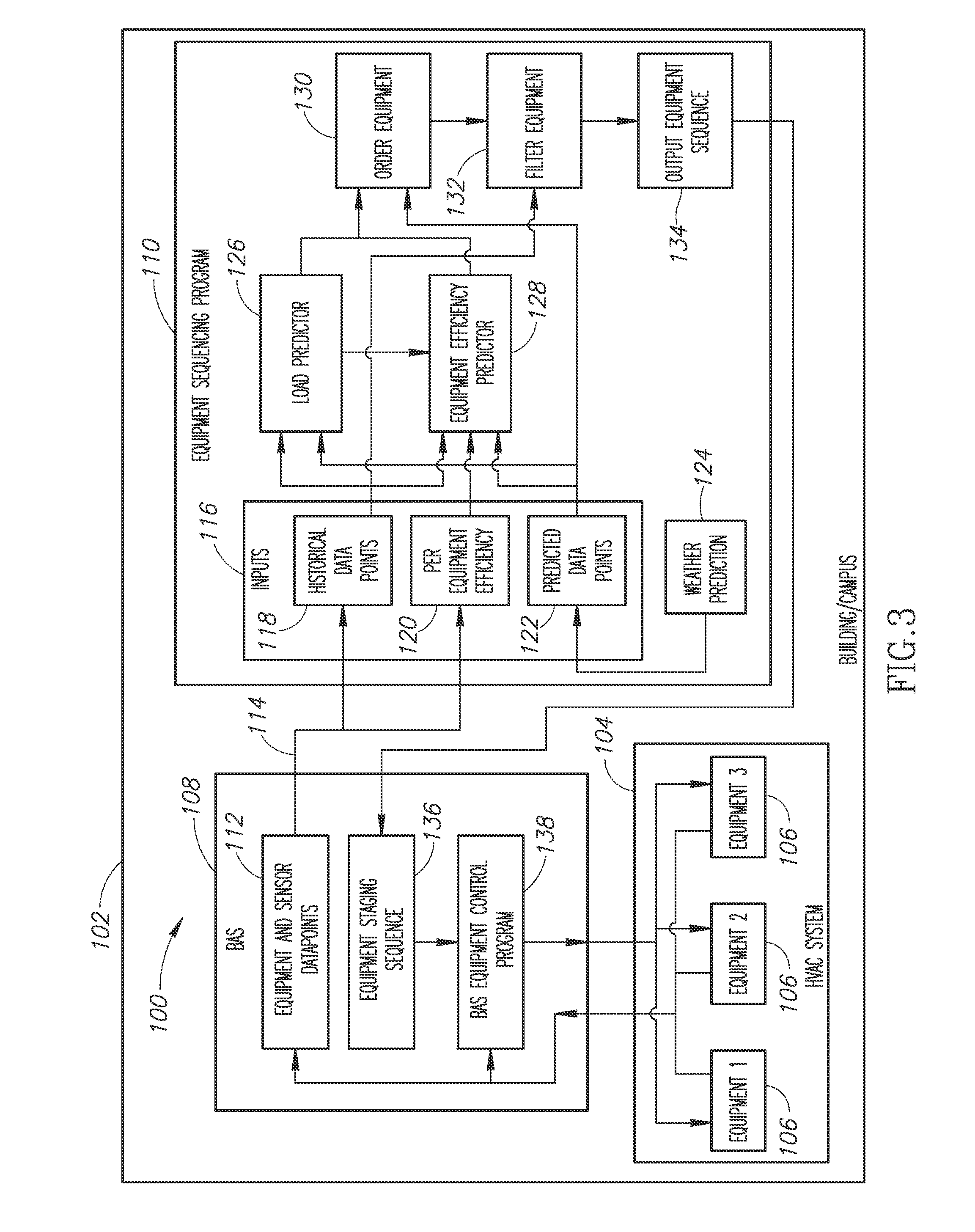
[0028]In the following description, certain specific details are set forth in order to provide a thorough understanding of various embodiments of the invention. However, one skilled in the art will understand that the invention may be practiced without these details. In other instances, well-known structures associated with HVAC systems; automation systems (e.g., building automation systems referred to as BASs) air handler units (AHUs) such as, but not limited to terminal units (also called fan coil units), packaged units or rooftop units, and various equipment used in HVAC systems such as, but not limited to, controllable valves, heating and cooling coils, various types of sensors; controllers and processors; communication networks; various computing and / or processing systems; chillers, fans, various HVAC system equipment operational parameters and set points, data points or data points; and methods of operating any of the above with respect to one or more buildings have not necess...


PUM


Abstract

Systems and methods for sequencing HVAC equipment of an HVAC system using data recorded in situ to build a model capable of making predictions about equipment efficiency and using that information, in combination with predictions about building load, to produce an operational sequence for the HVAC equipment that promotes an improved or optimized overall energy efficiency for the HVAC system. In one embodiment, the process is automated and utilizes Bayesian computational models or algorithms to generate are initial sequence. The process reduces engineering hours and may advantageously provide a means to predict potential sequencing problems for similar types of HVAC equipment.

Description

FIELD OF THE INVENTION[0001]The present invention generally relates to systems and methods for controlling and scheduling equipment in HVAC systems by predicting cooling loads, heating loads and equipment efficiencies using historical load and efficiency data recorded in situ by building sensors, a building automation system (BAS), an equipment automation system or some combination thereof.BACKGROUND[0002]Many buildings employ an HVAC system to maintain a comfortable environment. The HVAC system provides heating and cooling for the buildings. Conventionally, local engineering knowledge is used to produce a sequencing that arranges equipment (chillers, pumps, etc.) by their energy efficiency such as using the least efficient equipment only under the most extreme circumstances. To achieve a better energy efficiency and energy savings for the HVAC system, it is typically advantageous to use the equipment with the higher efficiency before bringing on other equipment that uses more energ...

Claims


Application Information

Patent Timeline
Patent Type & Authority Applications(United States)
IPC IPC(8): G05D23/19H04L12/28
CPCH04L12/2816G05D23/1917F24F11/30F24F11/62F24F11/46F24F11/64
Inventor JONES, THOMASDEMPSTER, IANMATTHYS, CLARKCHEN, PENG
Owner OPTIMUM ENERGY
Why Eureka
Try Eureka