Information processing method for generating encoded signal for visible light communication

a technology of information processing and encoded signals, applied in the direction of selective content distribution, electrical equipment, close-range type systems, etc., can solve the problems of insufficient computational performance of home electric appliances to have a communication function, limited conventional methods, and insufficient computational performance of home electric appliances to achieve a communication function. , to achieve the effect of low computational performan

Active Publication Date: 2016-06-30
PANASONIC INTELLECTUAL PROPERTY CORP OF AMERICA
View PDF2 Cites 69 Cited by
  • Summary
  • Abstract
  • Description
  • Claims
  • Application Information

AI Technical Summary

Benefits of technology

[0009]According to an embodiment of the present disclosure, a non-transitory computer-readable recording medium storing an information processing program or a...

Problems solved by technology

However, there are home electric appliances whose computational performance is insufficient to have a communication function, and home electric appliances which do not have a communicati...

Method used


Image

  • Information processing method for generating encoded signal for visible light communication
  • Information processing method for generating encoded signal for visible light communication
  • Information processing method for generating encoded signal for visible light communication

Examples


embodiment 1

[0509]The following describes Embodiment 1.

Observation of Luminance of Light Emitting Unit

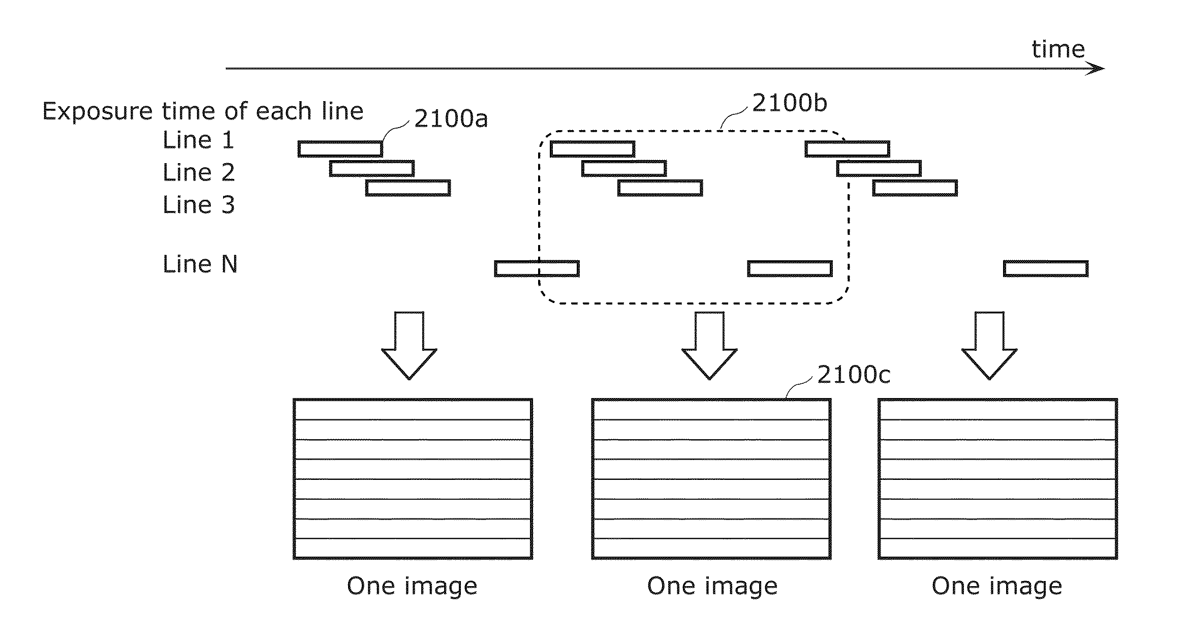
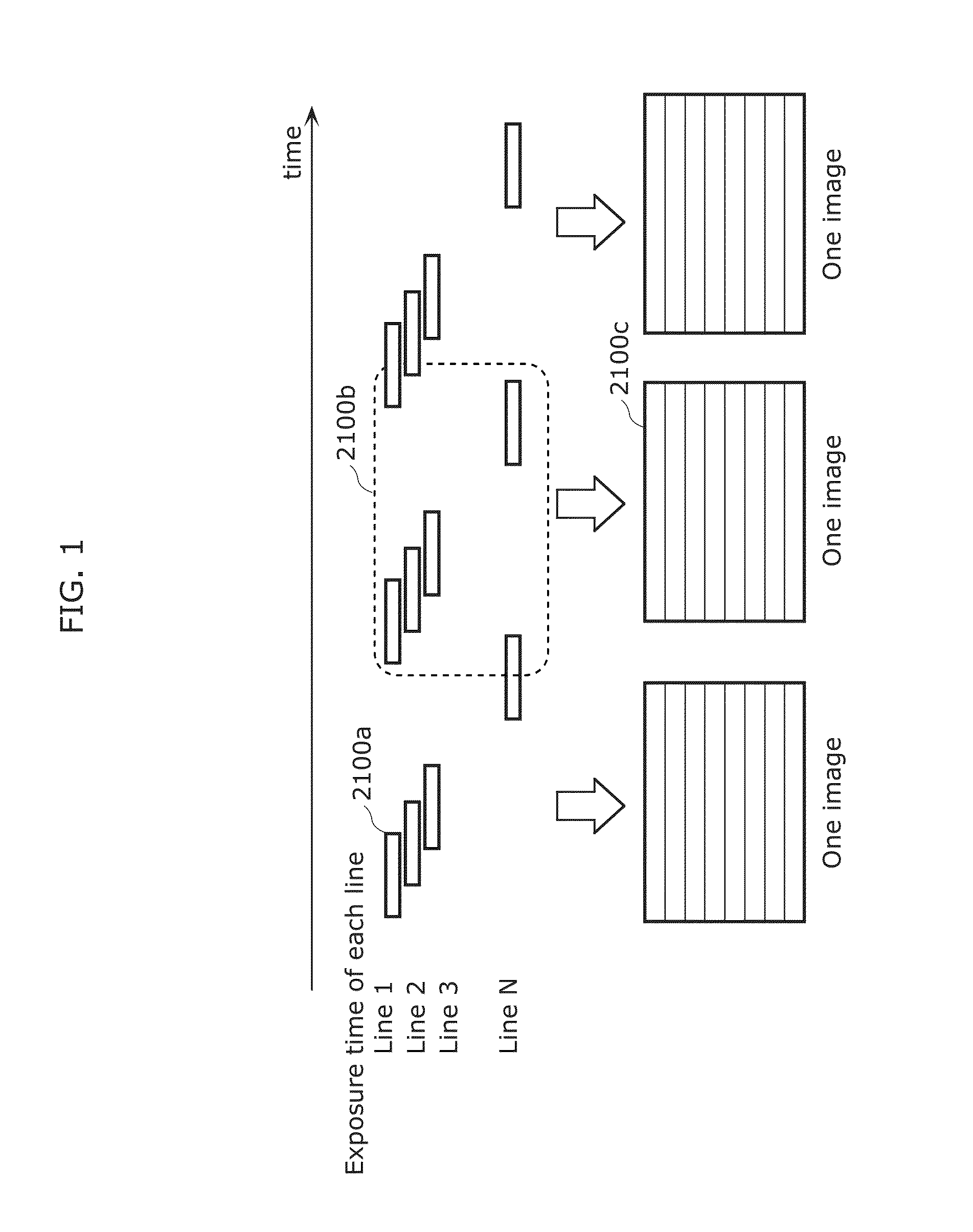
[0510]The following proposes an imaging method in which, when capturing one image, all imaging elements are not exposed simultaneously but the times of starting and ending the exposure differ between the imaging elements. FIG. 1 illustrates an example of imaging where imaging elements arranged in a line are exposed simultaneously, with the exposure start time being shifted in order of lines. Here, the simultaneously exposed imaging elements are referred to as “exposure line”, and the line of pixels in the image corresponding to the imaging elements is referred to as “bright line”.

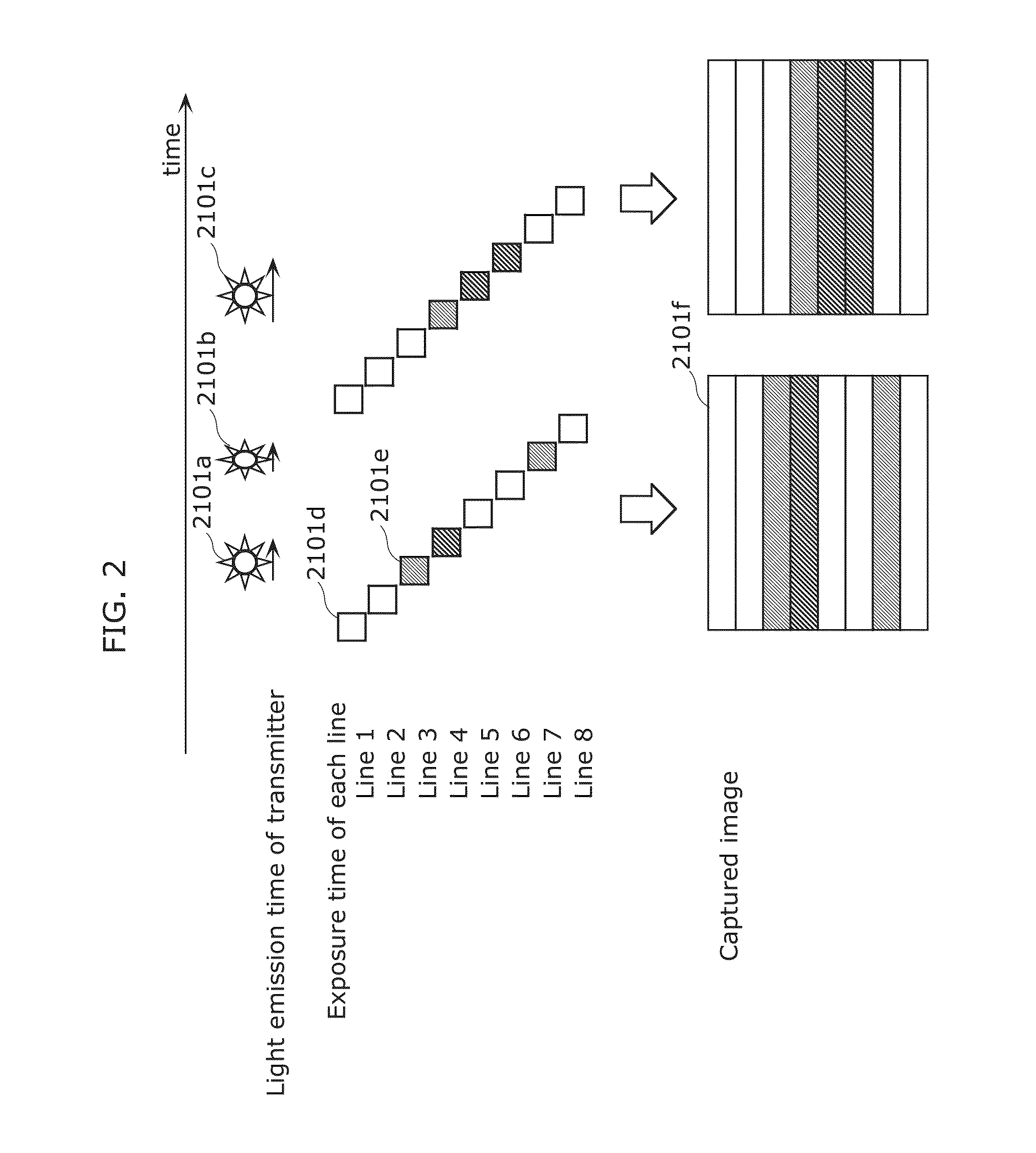
[0511]In the case of capturing a blinking light source shown on the entire imaging elements using this imaging method, bright lines (lines of brightness in pixel value) along exposure lines appear in the captured image as illustrated in FIG. 2. By recognizing this bright line pattern, the luminance change of the light ...

embodiment 2

[0542]This embodiment describes each example of application using a receiver such as a smartphone which is the information communication device K90 and a transmitter for transmitting information as a blink pattern of the light source such as an LED or an organic EL device in Embodiment 1 described above.

[0543]FIG. 7 is a diagram illustrating an example of each mode of a receiver in this embodiment.

[0544]In the normal imaging mode, a receiver 8000 performs imaging at a shutter speed of 1 / 100 second as an example to obtain a normal captured image, and displays the normal captured image on a display. For example, a subject such as a street lighting or a signage as a store sign and its surroundings are clearly shown in the normal captured image.

[0545]In the visible light communication mode, the receiver 8000 performs imaging at a shutter speed of 1 / 10000 second as an example, to obtain a visible light communication image. For example, in the case where the above-mentioned street lightin...

embodiment 3

[0694]This embodiment describes each example of application using a receiver such as a smartphone and a transmitter for transmitting information as a blink pattern of an LED, an organic EL device, or the like in Embodiment 1 or 2 described above.

[0695]FIG. 54 is a flowchart illustrating an example of operation of a receiver in Embodiment 3.

[0696]First, a receiver receives a signal by an illuminance sensor (Step 8101). Next, the receiver obtains information such as position information from a server, based on the received signal (Step 8102). The receiver then activates an image sensor capable of capturing the light reception direction of the illuminance sensor (Step 8103). The receiver receives all or part of a signal by the image sensor, and determines whether or not all or part of the signal is the same as the signal received by the illuminance sensor (Step 8104). Following this, the receiver estimates the position of the receiver, from the position of the transmitter in the captur...


PUM


Abstract

An information processing program causes a computer to execute: encoding information to be transmitted, to determine a luminance change frequency; and outputting a signal of the determined luminance change frequency to cause a light emitter to change in luminance according to the determined luminance change frequency to transmit the information. In the encoding, each of a first frequency and a second frequency different from the first frequency is determined as the luminance change frequency. In the outputting, each of a signal of the first frequency and a signal of the second frequency is output as the signal of the determined luminance change frequency, to cause the light emitter to change in luminance according to the first frequency during a first time and change in luminance according to the second frequency during a second time different from the first time after the first time elapses.

Description

BACKGROUND[0001]1. Technical Field[0002]The present disclosure relates to a method of communication between a mobile terminal such as a smartphone, a tablet terminal, or a mobile phone and a home electric appliance such as an air conditioner, a lighting device, or a rice cooker.[0003]2. Description of the Related Art[0004]In recent years, a home-electric-appliance cooperation function has been introduced for a home network, with which various home electric appliances are connected to a network by a home energy management system (HEMS) having a function of managing power usage for addressing an environmental issue, turning power on / off from outside a house, and the like, in addition to cooperation of AV home electric appliances by internet protocol (IP) connection using Ethernet® or wireless local area network (LAN). However, there are home electric appliances whose computational performance is insufficient to have a communication function, and home electric appliances which do not h...

Claims


Application Information

Patent Timeline
IPC IPC(8): H04B10/116
CPCH04B10/116H04N21/436
Inventor AOYAMA, HIDEKIOSHIMA, MITSUAKINAKANISHI, KOJIMAEDA, TOSHIYUKIUEKI, AKIHIROMIYOSHI, KENGOMUKAI, TSUTOMU
Owner PANASONIC INTELLECTUAL PROPERTY CORP OF AMERICA
Why Eureka
Try Eureka