Underground coal gasification furnace and underground coal gasification method

a gasification furnace and underground coal technology, applied in the direction of surface mining, wellbore/well accessories, construction, etc., can solve the problems of poor directivity of air fracturing drilling blockage, etc., to eliminate the defects in the gasification production stage, slow penetration speed, and unstable structure

Inactive Publication Date: 2016-07-07
ENN COAL GASIFICATION MINING
View PDF0 Cites 13 Cited by
  • Summary
  • Abstract
  • Description
  • Claims
  • Application Information

AI Technical Summary

Benefits of technology

[0010]Aiming to the technical problems in the prior art, an object of the invention is to provide an underground coal gasification furnace, and underground coal gasification process, so as to at least eliminate the defects in the gasification stage of production in the prior art, e.g., slow penetration speed and unstable structure.
[0031]The underground coal gasification furnace and the underground coal gasification according to the present invention have the beneficial effects: eliminating the defects in gasification production stage in the prior art, e.g., slow penetration speed, and unstable structure.

Problems solved by technology

Drawbacks of the prior art I lie in the poor directivity of the air fracturing and slow penetration speed.
Disadvantages of the prior art II lie that: ① the gasification furnace is difficult to build, the structure is not stable enough, and it is not easy to realize the connection of one horizontal directional drilling well with a plurality of vertical bores, even if it is achieved, there is a risk of drilling blockage if they are not used as soon as possible later; ② in the penetration-production cycle, the operation is difficult.
Multiple rows of vertical wells require to be penetrated by means of high pressure combustion, and the operation is difficult in the constant switching cycle between high pressure combustion penetration and gasification production.

Method used


Image

  • Underground coal gasification furnace and underground coal gasification method
  • Underground coal gasification furnace and underground coal gasification method
  • Underground coal gasification furnace and underground coal gasification method

Examples


example 1

[0048]The underground coal gasification furnace and the underground coal gasification process according to the present invention are explained by taking bituminous coal seam having buried depth of 500 m and horizontal thickness of 10 m at some place as an example.

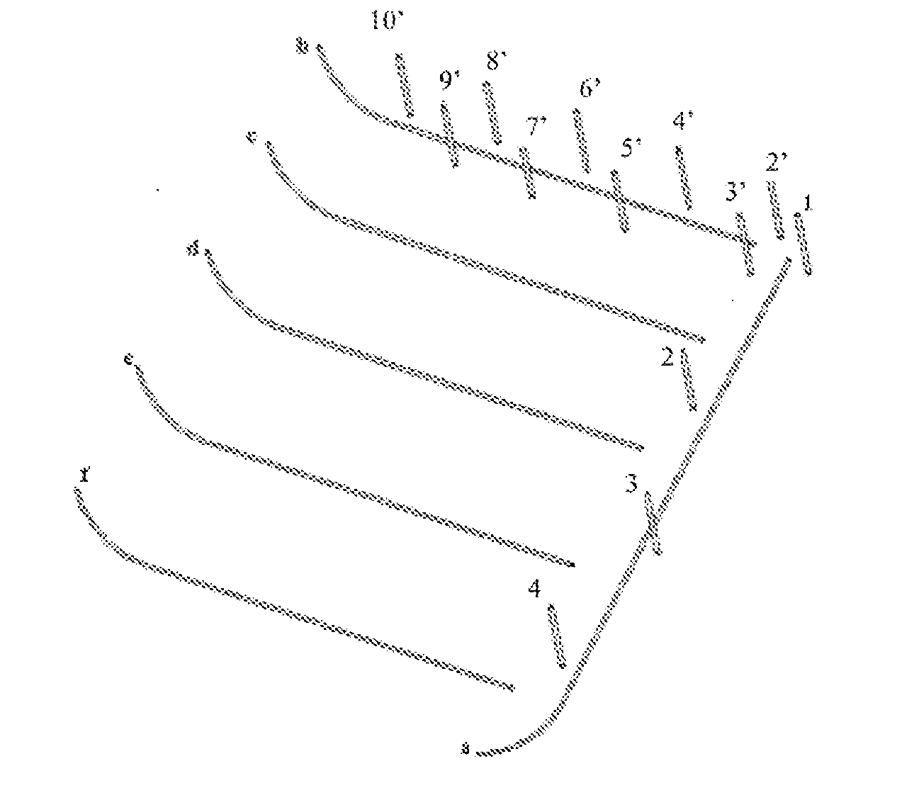
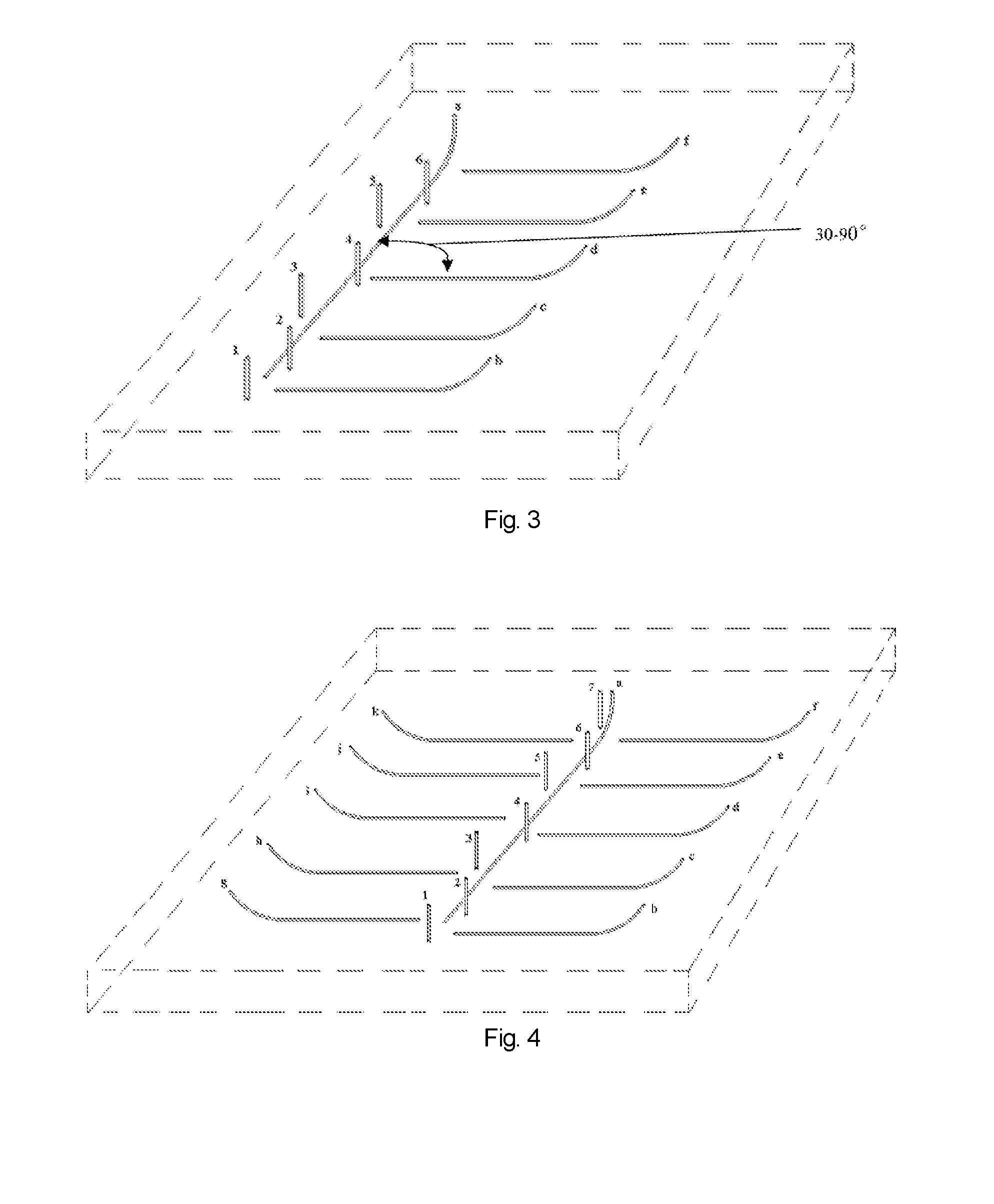
[0049]Firstly, referring to FIG. 4, a first vertical drilling well 1 is drilled to the middle lower part of the coal seam in the selected area for constructing the underground gasification furnace; the first horizontal directional drilling well a is drilled against the developing direction of cracks in coal seam towards the first vertical drilling well 1; the first horizontal directional drilling well a has a 250 m horizontal bore hole at the middle lower part of the coal seam. The second vertical drilling wells 2-7 are drilled into the middle lower part of the coal seam at a distance of about 5 m from both sides of the first horizontal directional drilling well a, which are spaced from each other at a distance of 25 m. The...

example 2

[0055]The underground coal gasification furnace and the underground coal gasification process according to the present invention are explained by taking lignite coal seam having buried depth of 300 m and horizontal thickness of 8 m at some place as an example.

[0056]Firstly, the developing direction of cracks in coal seam is determined according to geological data in the selected coal seam area for underground gasification, as shown by arrow in FIG. 5. At one selected point, a first vertical drilling well 1 is drilled to the middle lower part of the coal seam; a second vertical drilling well is drilled into the middle lower part of the coal seam in the developing direction of cracks in coal seam at interval of about 35 m and is numbered as 2, 3, 4, 5, 6; the first horizontal directional drilling well a is drilled against the developing direction of cracks in coal seam towards the first vertical drilling well 1; the horizontal section of the drilling well has a length of about 250 m a...

example 3

[0060]The underground coal gasification furnace and the underground coal gasification process according to the present invention are explained by taking sub-bituminous coal seam having buried depth of 600 m and horizontal thickness of 12 m at some place as an example.

[0061]Firstly, referring to FIG. 6, a first vertical drilling well 1 is drilled to the middle lower part of the coal seam in the selected area for constructing the underground gasification furnace; the first horizontal directional drilling well a is drilled against the developing direction of cracks in coal seam towards the first vertical drilling well 1; the first horizontal directional drilling well a has a horizontal bore hole with a length of 250 m at the middle lower part of the coal seam. The second vertical drilling wells 2-3 are drilled into the middle lower part of the coal seam at a distance of 5-15 m from one side of the first horizontal directional drilling well a at intervals of about 100 m. The second vert...


PUM


Abstract

An underground coal gasification furnace comprises an ignition system and a gas injection system. The ignition system is provided with a first vertical drilling well and a first horizontal directional drilling well in communication with the first vertical drilling well. The gas injection system is provided with a second drilling well introduced into a coal seam. At least one second horizontal directional drilling wells of a horizontal section in the coal seam serves as the second drilling well. Also provided is an underground coal gasification method. The method comprises: enabling a flaming fire region of a first horizontal directional drilling well to withdraw in a second horizontal directional drilling well until withdraw to near a coal feeding point. The underground coal gasification furnace eliminates the defects of low cut-through speed and unstable structure in a gasification production stage in the prior art.

Description

TECHNICAL FIELD[0001]The present invention relates to an underground gasification furnace and an underground coal gasification (UCG) method.BACKGROUND[0002]UCG relates to a process, in which the underground coal is burned under control and a combustible gas is produced by means of thermal effect and chemical reaction of coal. The underground gasification furnace is usually formed by an injection well, a gasification channel, a production well and some auxiliary monitoring wells. The gasifying agent is injected through the injection well and performs complex thermal chemical reaction with coal in the gasification channel, and the produced gas is transported to the ground through the production well.[0003]Here the type of the underground gasification furnace in narrow sense refers to the shape of the gasification channel, and in broad sense to the shape of channel, which is formed in dependence upon the type of the bore used in underground gasification, mutual position, usage and the ...

Claims


Application Information

Patent Timeline
Patent Type & Authority Applications(United States)
IPC IPC(8): E21B43/295E21B43/30
CPCE21B43/305E21B43/295E21B43/006
Inventor CHEN, FENGLIU, GANGPAN, XIA
Owner ENN COAL GASIFICATION MINING
Why Eureka
Try Eureka