Deployable Reflectarray Antenna Structure

a technology of reflector array and antenna structure, which is applied in the direction of antenna details, antenna adaptation in movable bodies, antennas, etc., can solve the problems of difficult to understand the deployment kinematics and reliability challenges, complicated and/or expensive feed network and amplifier structure, etc., to facilitate the transition of electrical elements and facilitate the positioning of electrical elements.

Active Publication Date: 2016-07-07
M M A DESIGN
View PDF46 Cites 26 Cited by
  • Summary
  • Abstract
  • Description
  • Claims
  • Application Information

AI Technical Summary

Benefits of technology

[0007]In one embodiment, the deployable reflectarray antenna structure includes a pair of electrical elements and a deployment mechanism for transitioning the pair of electrical elements from an undeployed state in which the electrical elements are not positioned relative to one another to function in a reflectarray antenna towards a deployed state in which the electrical elements are positioned relative to one another to function in a reflectarray antenna. To facilitate the transition of the electrical elements from the undeployed state towards the deployed state, a tape is employed in which one end of the tape is operatively connected to one of the electrical elements. In operation, the tape transitions from undeployed state in which the ends of the tape are relatively close to one another to a deployed sta

Problems solved by technology

However, the phased-array antenna typically requires a complicated and/or expensive feed network and amplifier structures.
Characteristic of such a dep

Method used


Image

  • Deployable Reflectarray Antenna Structure
  • Deployable Reflectarray Antenna Structure
  • Deployable Reflectarray Antenna Structure

Examples


Embodiment Construction

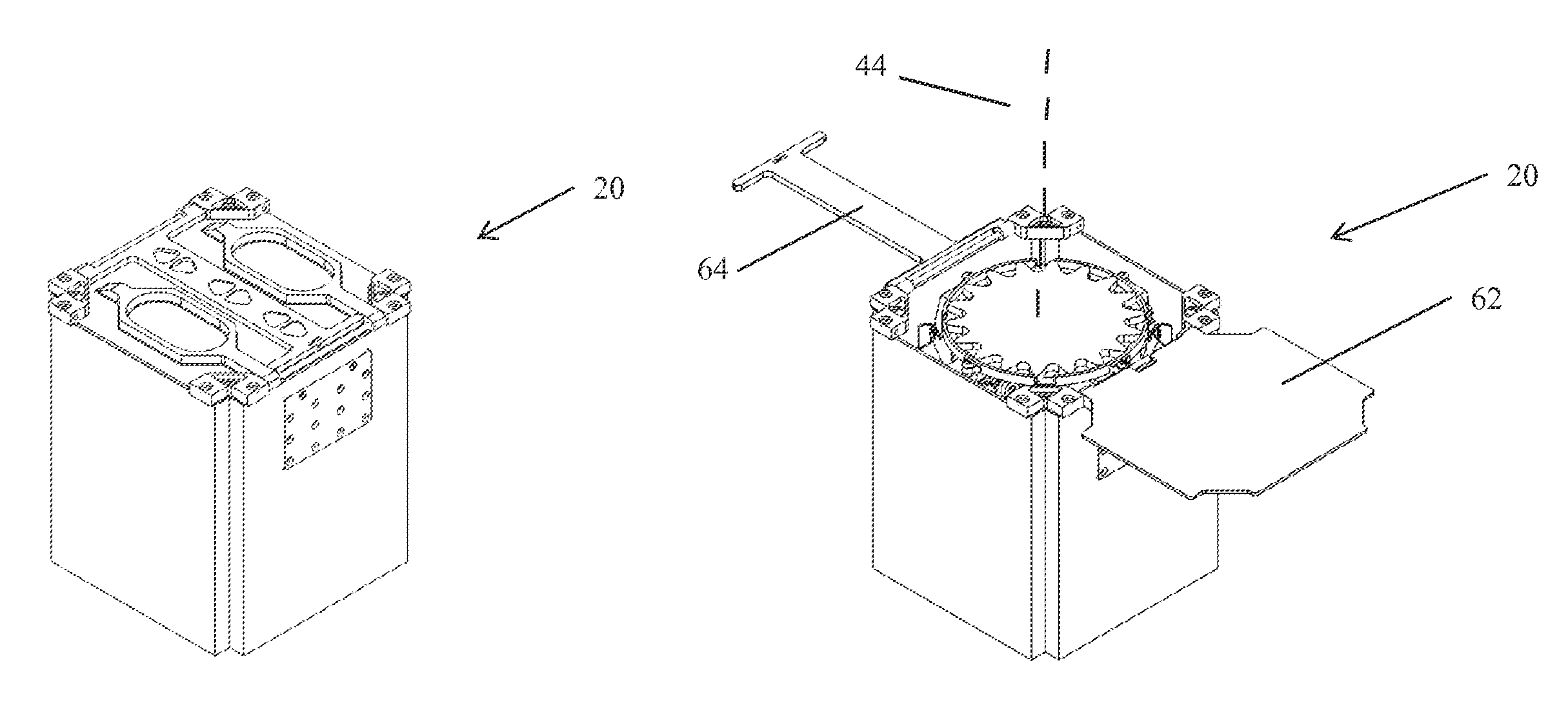
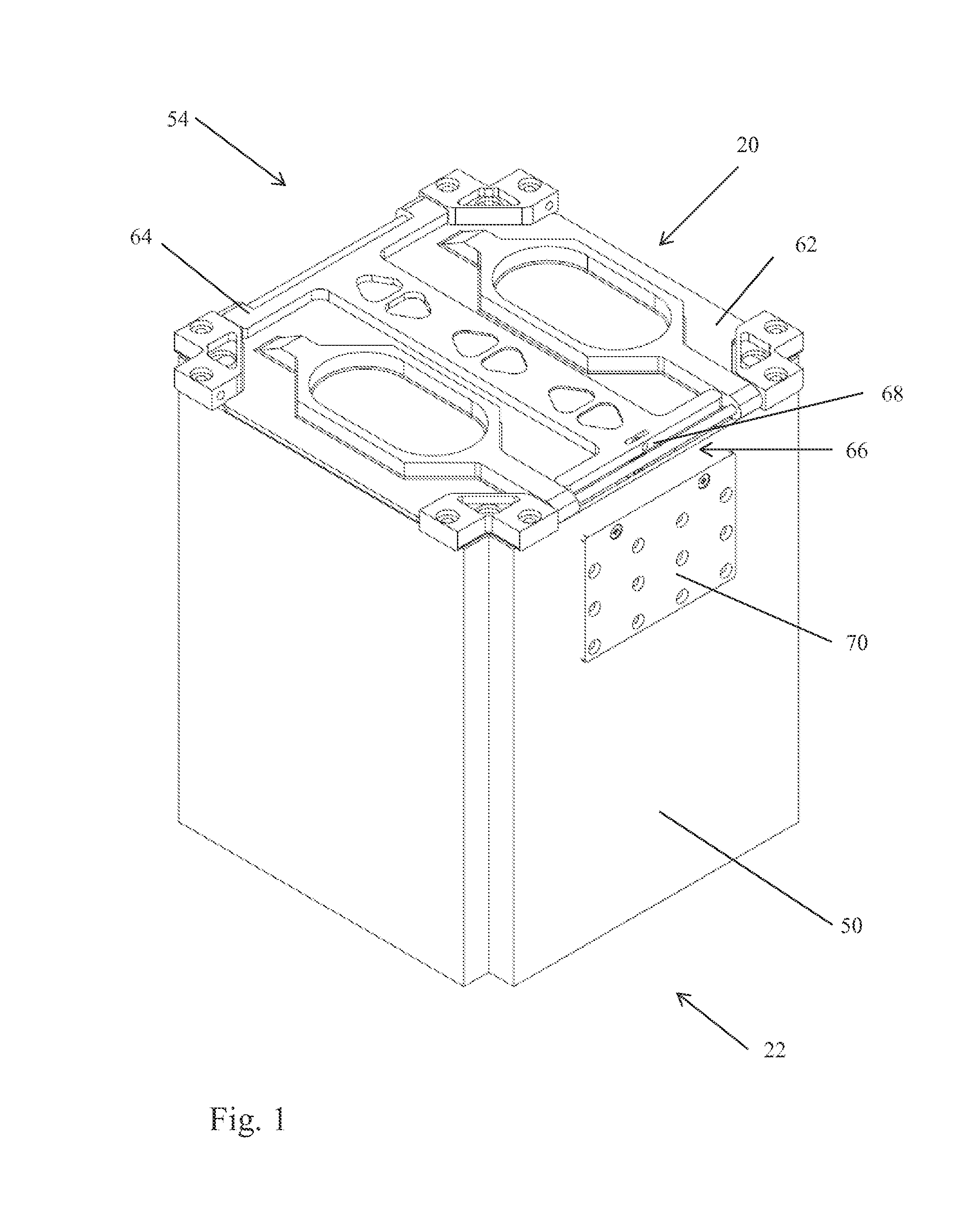
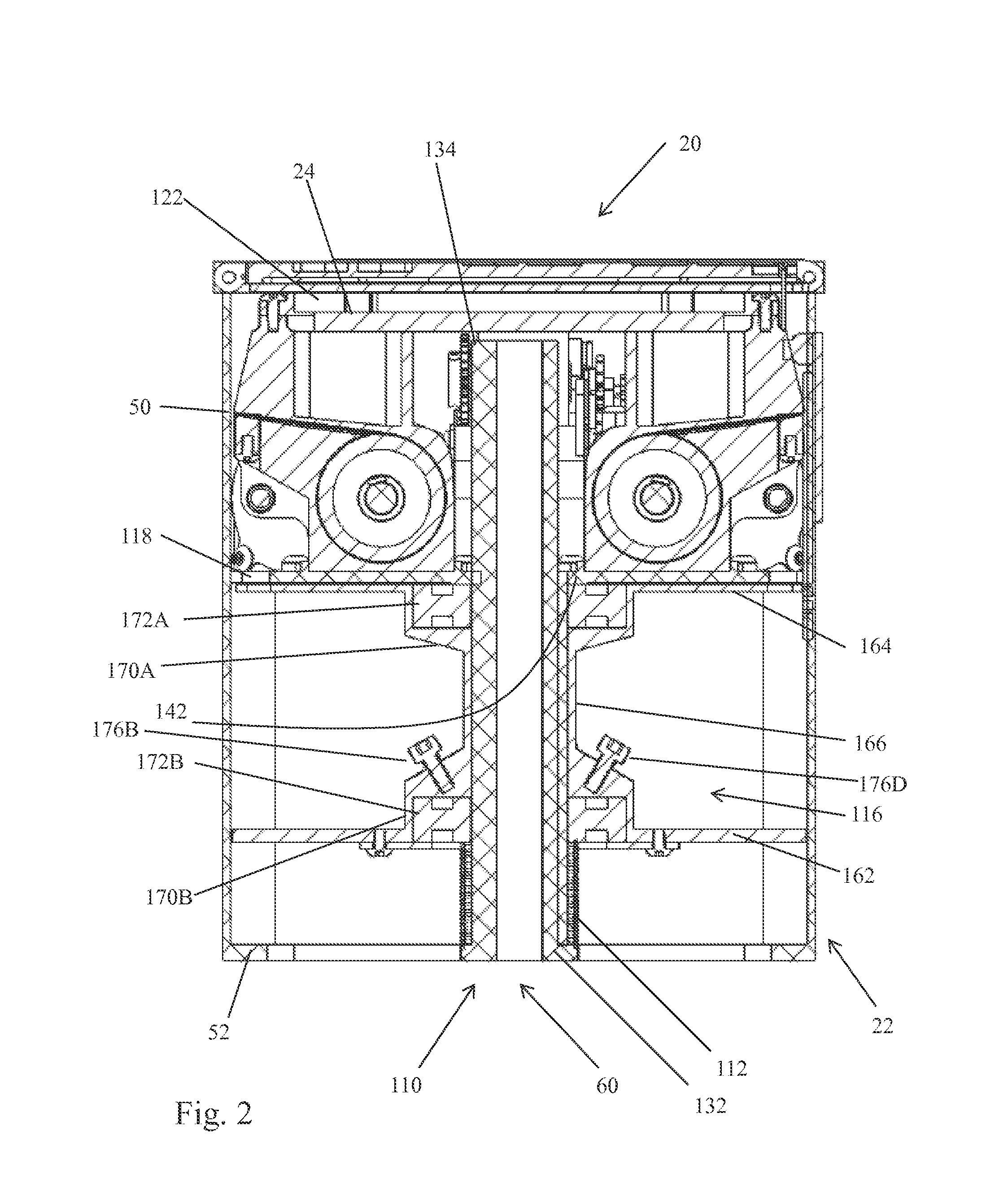
[0030]With reference to FIGS. 1-5 and 18A-18D, an embodiment of a deployable reflectarray antenna structure 20 (hereinafter referred to as “the deployable reflectarray 20”) is described. The deployable reflectarray 20 conforms to the CubeSat design specification. More specifically, the deployable reflectarray 20 conforms to a 1U CubeSat design specification, which requires the deployable reflectarray 20 be embodied within a cube that is 10 cm on a side and has a mass of no more than 1.33 kg. Although the deployable reflectarray 20 conforms to the CubeSat 1U design specification, it should be appreciated that adaptation to other form factors and mass requirements is feasible.

[0031]The deployable reflectarray 20 includes a canister 22, a feed antenna 24, a first flexible electrical element 26, a second flexible electrical element 28, and a deployment mechanism 30. Generally, the canister 22 stores the feed antenna 24, first and second flexible electrical elements 26, 28 and the deploy...


PUM


Abstract

The invention is directed to deployable reflectarray antenna structure. In one embodiment, the deployable reflectarray antenna structure includes a pair of flexible electrical elements, a feed antenna, and a deployment mechanism that employs a plurality of tapes to respectively transition the pair of flexible electrical elements from an undeployed state in which the elements are folded towards a deployed state in which the deployment mechanism and electrical elements cooperate to form a reflectarray and a subreflector of a reflectarray antenna structure. Further, the deployment mechanism also operates to position the reflectarray and subreflector relative to one another and to the feed antenna so as to realize a reflectarray antenna structure.

Description

FIELD OF THE INVENTION[0001]The invention relates to a deployable antenna structure and, more specifically, to a deployable reflectarray antenna structure.BACKGROUND OF THE INVENTION[0002]In applications requiring a high-gain antenna, there are at least three types of antennas that are typically employed, namely, a parabolic antenna, phased-array antenna, and a reflectarray antenna. The basic parabolic antenna includes a parabolic shaped reflector and a feed antenna located at the focus of the paraboloid and directed towards the reflector. The phased-array antenna includes multiple antennas with a feed network that provides a common signal to each of the antennas but with the relative phase of the common signal being fed to each of the antennas established such that the collective radiation pattern produced by the array of antennas is reinforced in one direction and suppressed in other directions, i.e., the beam is highly directional. In many applications, the phased-array antenna i...

Claims


Application Information

Patent Timeline
IPC IPC(8): H01Q1/12H01Q19/18
CPCH01Q19/18H01Q1/1235H01Q1/28H01Q1/08H01Q15/148H01Q15/161H01Q15/20
Inventor HARVEY, THOMAS J.HARVEY, TOBY J.SEAL, LESLIE A.
Owner M M A DESIGN
Why Eureka
Try Eureka