Correction of depth images from t-o-f 3D camera with electronic-rolling-shutter for light modulation changes taking place during light integration

a technology of depth image and light modulation, which is applied in the field of correction of depth image from tof 3d camera with electronic roll-shutter, can solve the problems of limiting the spatial resolution of sensors with demodulating pixels, difficult to combine these two functions in very small pixels, and complicated relation between an array of light-sensing pixels and a digital image ultimately obtained from it, so as to achieve fast frame rate and reduce blinking motion artifact between aggregate images

Active Publication Date: 2016-07-07
SAMSUNG ELECTRONICS CO LTD
View PDF1 Cites 37 Cited by
  • Summary
  • Abstract
  • Description
  • Claims
  • Application Information

AI Technical Summary

Benefits of technology

[0012]In embodiments, a T-O-F depth imaging device renders a depth image of an object that has corrected depth values. The device includes a pixel array that uses an Electronic Rolling Shutter (ERS) scheme. The device also includes a light source that transmits towards the object light that is modulated at an operating frequency, and an optical shutter that opens and closes at the operating frequency. The optical shutter further modulates the light that is reflected from the object, before it reaches the pixel array. The transmission of the light and the operation of the shutter change phase relative to each other while at least one of the pixels is sensing the light it receives, which permits a faster frame rate. Depth is determined by the amount of light sensed by the pixels, and a correction is computed to compensate for the changing phase.
[0013]Accordingly, embodiments provide a way to avoid the above-mentioned inefficiency in the use of pixels at T-O-F ranging systems using global demodulators and ordinary ERS image sensors.
[0014]In embodiments, a T-O-F depth imaging device performs corrections to T-O-F depth image frames rendered for an object. The device includes a pixel array and a light source that transmits towards the object light that is modulated at an operating frequency. The modulated light is reflected from the object and is sensed by the pixel array, which generates raw data frames for depth at different phases. At least one composite data frame is calculated from nonzero contributions of two of the raw data frames that are for similar phases, and an aggregate image is computed from at least the composite data frame plus possibly some of the raw data frames. Thus a blinking motion artifact between aggregate images can be reduced.

Problems solved by technology

However, the relation between an array of light-sensing pixels and a digital image ultimately obtained from it can be quite complicated.
The latter may be present due to, for example, the absence of sufficiently near and sufficiently reflective objects in certain parts of the ranging device's FOV.
However, combining these two functions in very small pixels is difficult, which limits the spatial resolution of sensors with demodulating pixels.
However, holding on to this preference in an T-O-F depth imaging system combining a global demodulation function (provided, for instance, by an optical shutter) with a local light integration timing (e.g. the timing scheme known in the art as Electronic Rolling Shutter or ERS) may require an inefficient use of pixels, in the sense that successive light integrations in a particular pixel producing the “pure one-phase light intensity samples” may have to be separated by long periods of idle waiting for other pixels to complete their similar integrations.
If a pixel integrates light over significantly less than 100% of every interval between two consecutive integration starts, the pixel is used inefficiently.
Some of the disadvantages are unique to the combination of a global demodulator with local integration timing exemplified by the integration timing in ERS sensors.
The main disadvantage of this combination is its inability to produce raw frames consisting of “pure one-phase light intensity samples” at a maximum frame rate permitted by the ERS timing scheme.

Method used


Image

  • Correction of depth images from t-o-f 3D camera with electronic-rolling-shutter for light modulation changes taking place during light integration
  • Correction of depth images from t-o-f 3D camera with electronic-rolling-shutter for light modulation changes taking place during light integration
  • Correction of depth images from t-o-f 3D camera with electronic-rolling-shutter for light modulation changes taking place during light integration

Examples


first embodiment

[0147]FIG. 21 is a diagram for implementing corrections to T-O-F depth image frames according to a FIG. 21 is a timing diagram showing a sequence of depth frames rendered by computation from a sequence of acquired raw frames. Frame labels are shown above the acquired raw frames, which may apply to these raw frames. It will be understood that each raw frame might have more than one label, which may be based on which rendered frame the raw frame contributes at the time. In this example, first, second, third and fourth raw data frames can be suitably selected among those for 0°, 90°, 180° and 270°.

[0148]As can be seen, a processor can be configured to calculate a composite first frame ACP90(I+3) 2141 for 90°. Calculation may happen, for example, as seen in Equation 21. The calculation provides an average for two raw phase data frames at 90°. The average may be weighted evenly, or favoring one of the constituent raw data frames, as long as there are nonzero contributions from at least ...

second embodiment

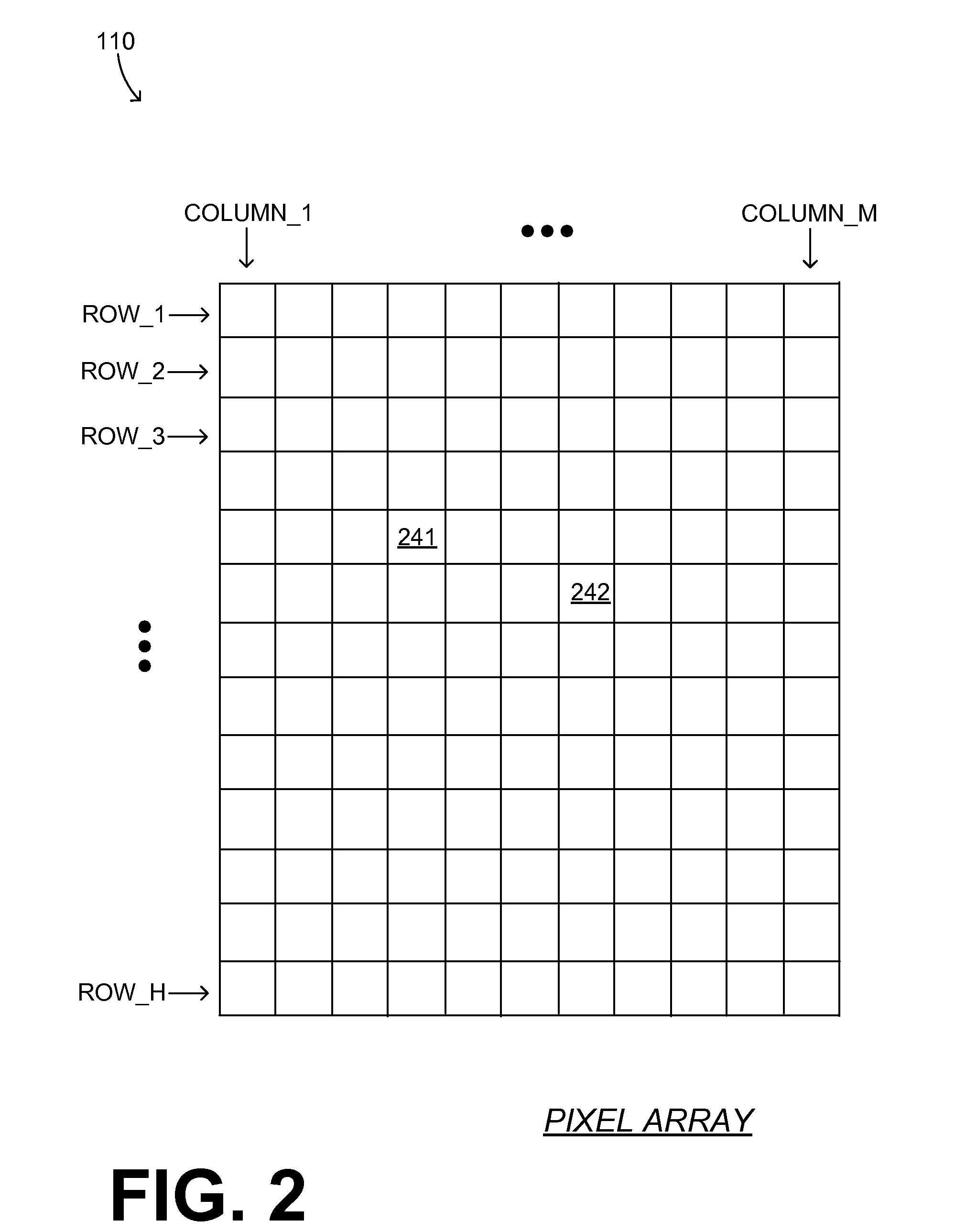
[0151]FIG. 22 is a diagram for implementing corrections to T-O-F depth image frames according to a It will be recognized that here the processor calculates both a composite first frame 2241 and also a composite second frame 2242. The aggregate image is computed also from the composite second frame 2242, and fewer pure raw frames.

third embodiment

[0152]FIG. 23 is a diagram for implementing corrections to T-O-F depth image frames according to a It will be recognized that here the processor calculates a composite first frame 2341, a composite second frame 2342, and also a composite third frame 2343. The aggregate image is computed from these three composite frames, and only one pure raw frame, but requires more calculations.

[0153]FIG. 24 is a table of frame labels that may be used according to embodiments.

[0154]FIG. 25 shows a flowchart 2500 for describing methods according to embodiments. The methods of flowchart 2500 may be implemented by embodiments.

[0155]According to an operation 2510, an illumination clock signal is generated. The illumination clock signal can be modulated at an operating frequency.

[0156]According to another operation 2520, light can be emitted by a light source towards an object. The light can be emitted responsive to the illumination clock signal, and therefore modulated according to the illumination c...


PUM


Abstract

In embodiments, a T-O-F depth imaging device renders a depth image of an object that has corrected depth values. The device includes a pixel array that uses an Electronic Rolling Shutter scheme. The device also includes a light source that transmits towards the object light that is modulated at an operating frequency, and an optical shutter that opens and closes at the operating frequency. The optical shutter further modulates the light that is reflected from the object, before it reaches the pixel array. The transmission of the light and the operation of the shutter change phase relative to each other while at least one of the pixels is sensing the light it receives, which permits a faster frame rate. Depth is determined by the amount of light sensed by the pixels, and a correction is computed to compensate for the changing phase.

Description

CROSS REFERENCE TO RELATED PATENT APPLICATIONS[0001]This patent application claims priority from U.S. Provisional Patent Application Ser. No. 62 / 100,464, filed on Jan. 6, 2015, the disclosure of which is hereby incorporated by reference.BACKGROUND[0002]Ranging devices are used for range sensing, i.e. measuring distances from these devices to objects or persons. Range sensing is also known as ranging, distance sensing or depth sensing. Certain ranging devices, sometimes referred to as imaging range sensors, can perform simultaneously multiple distance measurements in different directions within a certain solid angle or field of view (FOV). A set of distance values measured in this way can be converted into a 3-dimensional (3D) image of objects present in the FOV. This is why descriptions of imaging range sensors often resemble descriptions of more traditional cameras, producing 2-dimensional (2D) images that are relatively less informative about the shapes of imaged objects and more ...

Claims


Application Information

Patent Timeline
Patent Type & Authority Applications(United States)
IPC IPC(8): H04N13/02G01S17/89G01S7/4914G01S17/894
CPCH04N13/0296G01S17/89H04N13/0271H04N13/0253H04N13/021G01S17/36G01S7/4816G01S7/4914G01S17/894
Inventor WALIGORSKI, GREGORYOVSIANNIKOV, ILIAPARK, YONG-HWA
Owner SAMSUNG ELECTRONICS CO LTD
Why Eureka
Try Eureka