Hopper tee having drop opening with arcuate closure

a technology of arcuate closure and hopper tee, which is applied in the direction of mechanical equipment, transportation and packaging, branching pipes, etc., can solve the problems of affecting the performance of the hopper tee, and achieve the effect of reducing the downtim

Inactive Publication Date: 2016-07-14
BULK TANK
View PDF0 Cites 2 Cited by
  • Summary
  • Abstract
  • Description
  • Claims
  • Application Information

AI Technical Summary

Benefits of technology

[0017]This invention provides a directional hopper tee with an internally fluted vertical pipe blending into a horizontal pipe. The hopper tee has a vertical pipe with an opening that connects to a hopper, or bin, to receive bulk material into the tee and a horizontal pipe centered upon one end of the vertical pipe. The horizontal pipe has an inlet that receives bulk material and pressurized air from ahead of the hopper and an opposite outlet that discharges the bulk material already flowing in the horizontal pipe and that is received from the hopper through the vertical pipe. The vertical pipe has a flange that abuts the hopper and an opening in the flange that matches the opening of a valve on the hopper itself. At the opening, the vertical pipe begins to turn towards the outlet of the lower pipe with a flute. The flute begins immediately at the flange resulting in a vertical pipe with a curved shape towards the outlet and a square shape towards the inlet. The present invention raises the ground clearance of the horizontal pipe by at least one inch resulting in a hopper tee that clears at least 7 inches above the ground. The hopper tee of the invention also unloads up to and including 22% more products per minute than prior art tees during field use conditions. Alternate embodiments of the present invention provide a reinforced flange, a drop tee, and a low profile drop tee. The present invention aids in the unloading of bulk materials from various truck, rail, and ship transporters.

Problems solved by technology

Reduction in product surges leads to less instances of plugged unloading lines and the resultant downtime during an unload cycle.

Method used


Image

  • Hopper tee having drop opening with arcuate closure
  • Hopper tee having drop opening with arcuate closure
  • Hopper tee having drop opening with arcuate closure

Examples


Embodiment Construction

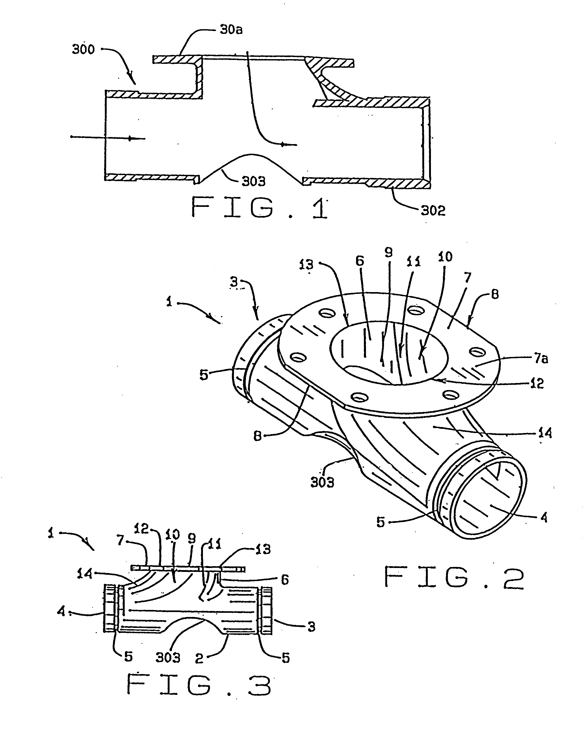
[0058]In referring to the drawings, FIG. 1 shows a drop tee, having an arcuate style of bottom, wherein the tee 300 includes a flanged vertical section 301, a horizontal or longitudinal section integrated into the structure of the tee, as noted at 302, and further incorporates that arcuate opening through its bottom, as at 303, that provides for unloading of the hopper bin or tank trailer directly through the shown attached tee 300.

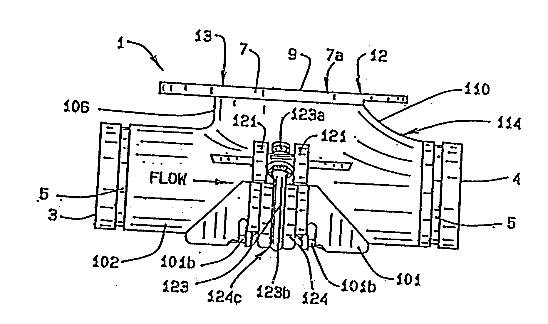
[0059]In referring to the drawings, FIG. 2 also shows the integral tee, generally known as a hopper tee, of the present invention 1 in a perspective view. The present invention has a generally transverse hollow pipe, hereinafter horizontal pipe 2, round in cross section and of a known diameter. The horizontal pipe has two opposed ends, one end being an inlet 3 that receives material sent into the hopper tee under pneumatic pressures from another source, and the opposite end being an outlet 4 that discharges material from the inlet and the materials as unl...


PUM


Abstract

A directional hopper tee has a fluted interior vertical pipe that merges into a horizontal pipe. The horizontal pipe has an inlet that may receive bulk material, and subject to pressurized air that conveys the bulk material through the hopper tee. Bulk material may be discharged from a hopper through the vertical pipe, for conveyance for discharge from the horizontal pipe of the tee. A closure gate or door is provided through the bottom of the tee, generally in alignment with the vertical pipe, to allow for discharge or dropping of the granular material directly downwardly through and from the tee. The arcuate door is hinged on one side, and is locked by a cam lock on the opposite side, when located into closure against the bottom of the tee, but can be forced opened, through its cam mechanism, to provide for opening of the arcuate door and allow a direct downward discharge of the granular bulk material, from any hopper, and through the drop opening of the tee, as required.

Description

CROSS REFERENCE TO RELATED APPLICATION[0001]This application is a continuation of patent application having Ser. No. 13 / 815,315, filed on Feb. 19, 2013, which claims priority to the non-provisional patent application having Ser. No. 13 / 200,625, filed on Sep. 27, 2011, which claims priority to the non-provisional patent application having Ser. No. 12 / 249,672, filed on Oct. 10, 2008, now U.S. Pat. No. 8,091,925, which latter application claims priority to the provisional application having Ser. No. 61 / 030,777, having a filing date of Feb. 22, 2008, which is related to U.S. Pat. No. 6,786,362, which also claims priority to that non-provisional patent application having Ser. No. 12 / 249,672, filed on Oct. 10, 2008, now U.S. Pat. No. 8,091,925; and also claims priority to application having Ser. No. 12 / 364,643, filed on Feb. 3, 2009, now U.S. Pat. No. 7,988,386; and this application also claims priority as a continuation-in-part to the application having Ser. No. 13 / 506,244, filed on Apr....

Claims


Application Information

Patent Timeline
Patent Type & Authority Applications(United States)
IPC IPC(8): B65D90/62B65D88/28F16L41/02
CPCB65D90/623B65D88/28F16L41/021
Inventor SISK, DAVID E.
Owner BULK TANK
Why Eureka
Try Eureka