Submersible pump and bearing arrangement

a technology of bearing arrangement and submersible pump, which is applied in the direction of bearing unit rigid support, machines/engines, liquid fuel engines, etc., can solve the problems of affecting the operation of the pump. , to achieve the effect of simple design, simple design and low cos

Active Publication Date: 2016-07-14
SULZER MANAGEMENT AG
View PDF4 Cites 4 Cited by
  • Summary
  • Abstract
  • Description
  • Claims
  • Application Information

AI Technical Summary

Benefits of technology

[0028]As already mentioned, the advantages of the submersible pump in accordance with the invention and of the bearing arrangement in accordance with the invention are that the bearing cover can be centered at the outer bearing ring of the bearing element or, with a plurality of bearing elements, the bearing cover can be centered at the outer bearing ring of the bearing element arranged directly at the bearing cover. The bearing cover is thereby centered better and all the outer bearing rings are completely tensioned in the longitudinal axial direction. The submersible pump and the bearing arrangement, in particular the bearing cover, can thus have a simpler design, can in particular have a simpler design from a construction aspect, and can be manuf

Problems solved by technology

On operating disturbances, overheating may arise and ignition sources can be produced in the pump, for example due to spark formation on a short-circuit.
If these sparks escape from the pump, they can ignite the gas and damage or destroy the structure in which the pump is installed, such as the pump, and the submersible pump.
The disadvantage of this apparatus is that it is very complex and expensive in manufacture from a construction aspect since additional components have to be designed and manufactured which make the bearing arrangement unnecessarily complicated.
In addition, more installation space is required in the submersible pump.
Other measures provide a formation of a gap between the bearin

Method used


Image

  • Submersible pump and bearing arrangement
  • Submersible pump and bearing arrangement
  • Submersible pump and bearing arrangement

Examples


Embodiment Construction

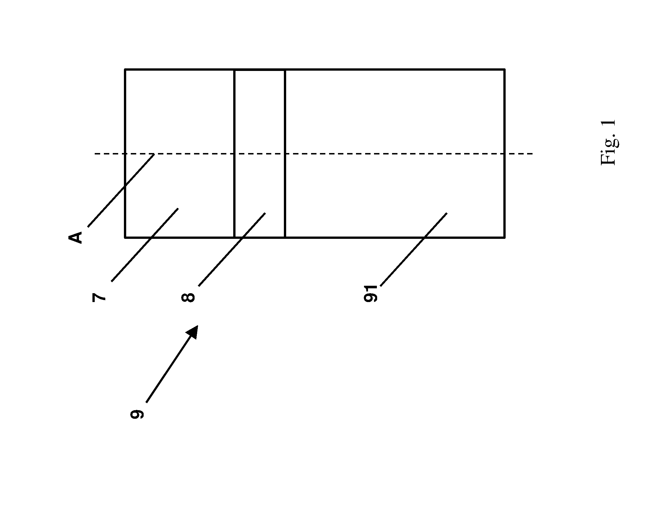
[0032]FIG. 1 shows a schematic representation of a first embodiment of a submersible pump 9 in accordance with the invention. The submersible pump 9 comprises a pump housing 91 having an impeller (not shown) arranged therein and comprises a motor housing 7 placed onto the pump housing 91 and having an electric motor (not shown) which is arranged therein and which drives the impeller via a rotor shaft (not shown). A shaft leadthrough 8 is arranged between the motor housing 7 and the pump housing 91 of the submersible pump 9. The shaft leadthrough 8 is passed through by the rotor shaft, with the shaft leadthrough 8 being formed by the bearing cover (see FIG. 2).

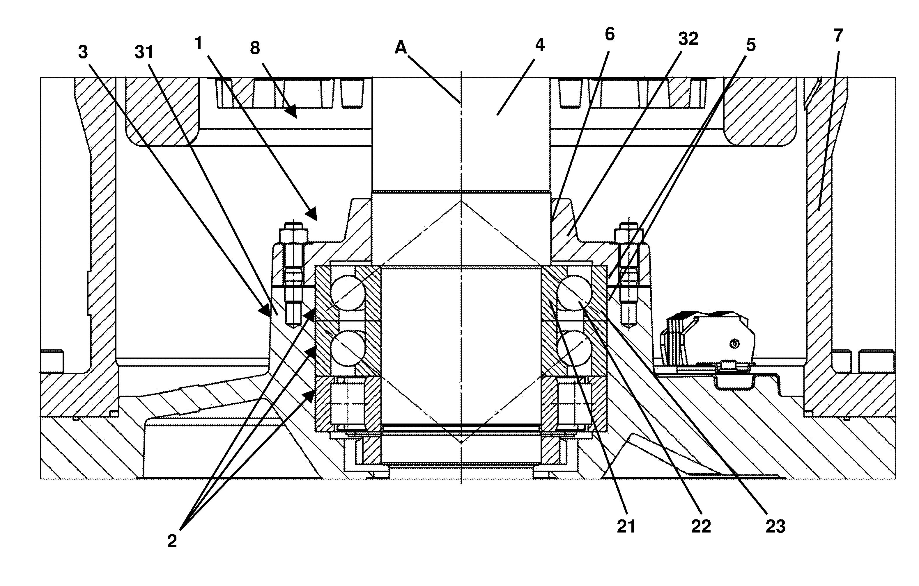
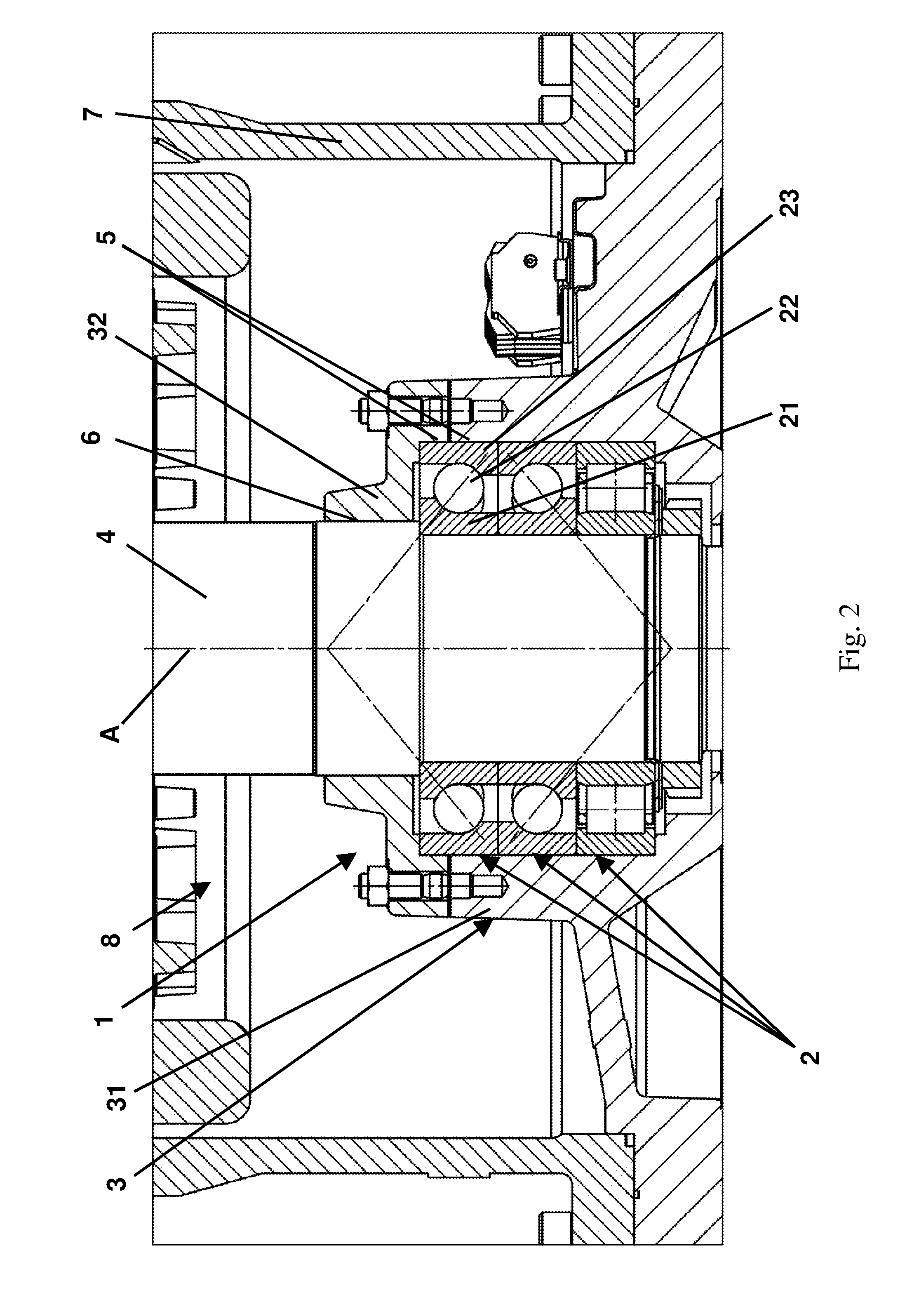
[0033]FIG. 2 shows a schematic representation of a first embodiment of a bearing arrangement 1 in accordance with the invention which is arranged in a submersible pump 9 in accordance with the invention. The rotor shaft 4 is rotatably supported in a bearing element 2 about the axis of rotation A extending in a longitudinal axia...


PUM


Abstract

A submersible pump includes a bearing arrangement and a rotor shaft. The bearing arrangement includes a bearing cover, a bearing flange, and one or more bearing elements, each bearing element having an inner bearing ring, an outer bearing ring and a roller element. The rotor shaft is rotatably supported in the one or more bearing element about an axis of rotation extending in a longitudinal axial direction so that the inner bearing ring is configured to rotate along with the rotor shaft in an operating state. The bearing element is arranged at the bearing flange such that the bearing cover tensions each outer bearing ring in a longitudinal axial direction and such that a peripheral gap having a predefined axial width is formed in a radial direction between the outer bearing ring and the bearing cover and between the outer bearing ring and the bearing flange.

Description

CROSS-REFERENCE TO RELATED APPLICATIONS[0001]This application claims priority to EP Application No. 15151015.3, filed Jan. 13, 2015, the contents of which is hereby incorporation herein by reference.FIELD OF THE INVENTION[0002]The invention relates to a submersible pump comprising a bearing arrangement. In particular, the invention relates to a submersible pump comprising a bearing arrangement with a bearing cover and one of more bearing elements.BACKGROUND OF THE INVENTION[0003]Known submersible pumps have a large number of precision components which require precise alignment, assembly and interaction among one another. Such known submersible pumps comprise a pump housing, a motor part having an electric motor arranged in a motor housing and having a hydraulic part with a pump wheel as well as having a shaft leadthrough which is arranged between the motor part and the hydraulic part and which is passed through by a rotor shaft.[0004]The submersible pump pumps a pump fluid, for exam...

Claims


Application Information

Patent Timeline
IPC IPC(8): F04D29/049F16C19/54F04D29/22F16C25/06F04D13/08F04D29/18
CPCF04D29/049F04D13/08F16C19/547F04D29/22F16C25/06F04D29/181F04D29/0467F04D15/0077F16C35/045F04D29/041F16C19/52F16C19/541H02K5/136H02K5/1732F16C35/067F16C2380/26F16C2360/44F16C2226/60F04D29/046
Inventor BECKER, KLAUS
Owner SULZER MANAGEMENT AG
Why Eureka
Try Eureka