Image display apparatus and method of manufacturing image display apparatus

Active Publication Date: 2016-07-14
SEIKO EPSON CORP
View PDF0 Cites 12 Cited by
  • Summary
  • Abstract
  • Description
  • Claims
  • Application Information

AI Technical Summary

Benefits of technology

The patent text describes a way to improve image quality by using a special arrangement of two beams to create an interference fringe. This fringe helps to reduce image light that may interfere with the eye's natural response. This technique can reduce deterioration of image quality caused by light interference between the left and right eyes.

Problems solved by technology

Accordingly, unintended and unnecessary light enters the left eye, and hence there arises a case where the quality of a displayed image is lowered such that a bright point (ghost image, for example) is seen.
Therefore, for example, deterioration of image quality caused by the image light for the right eye entering the left eye on the opposite side can be restricted.
In addition, deterioration of image quality caused by the image light for the left eye entering the right eye on the opposite side can be restricted.
Therefore, for example, deterioration of image quality caused by the image light for the right eye entering the left eye on the opposite side can be restricted.

Method used


Image

  • Image display apparatus and method of manufacturing image display apparatus
  • Image display apparatus and method of manufacturing image display apparatus
  • Image display apparatus and method of manufacturing image display apparatus

Examples


first embodiment

Configuration of Mounting-Type Image Display Apparatus

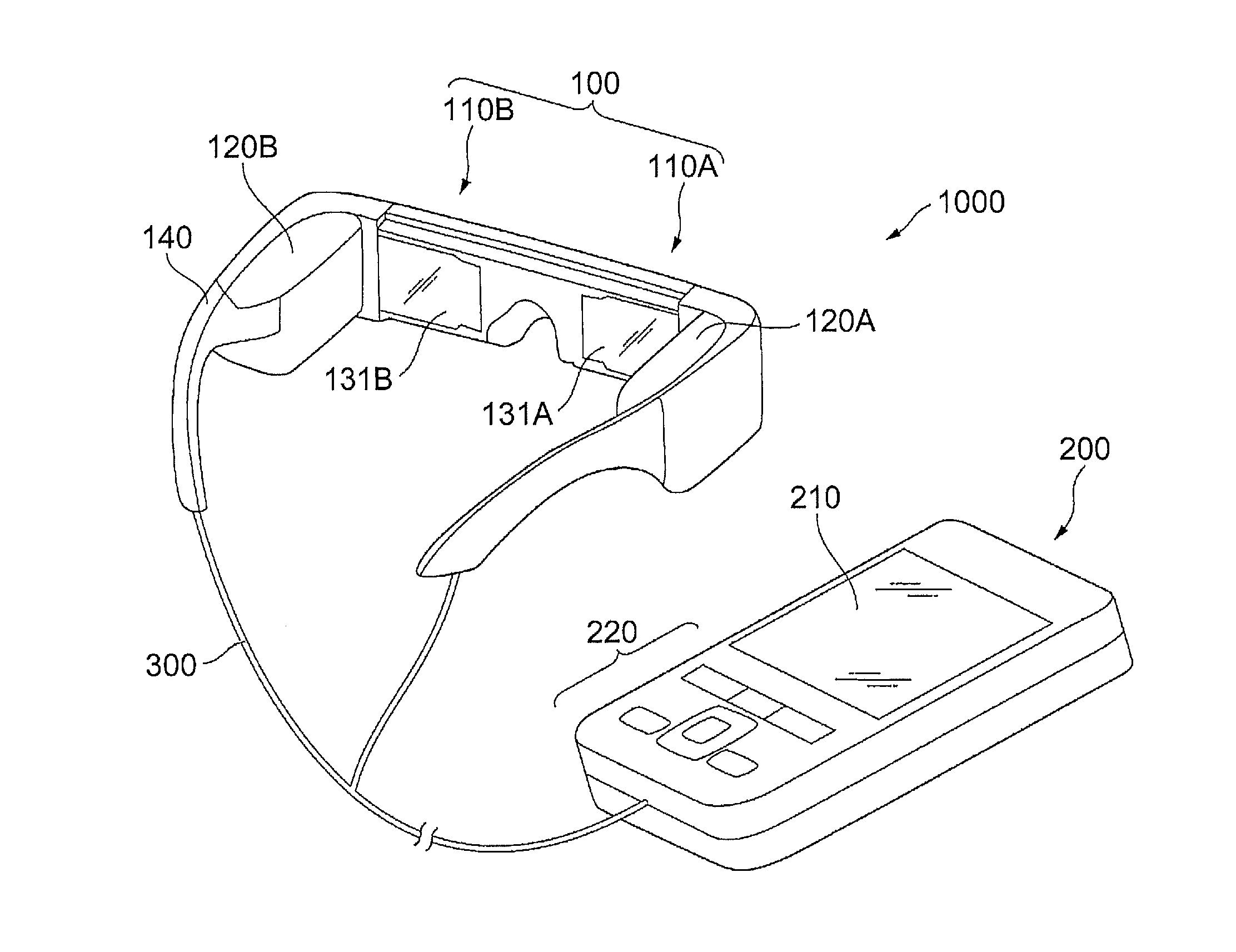
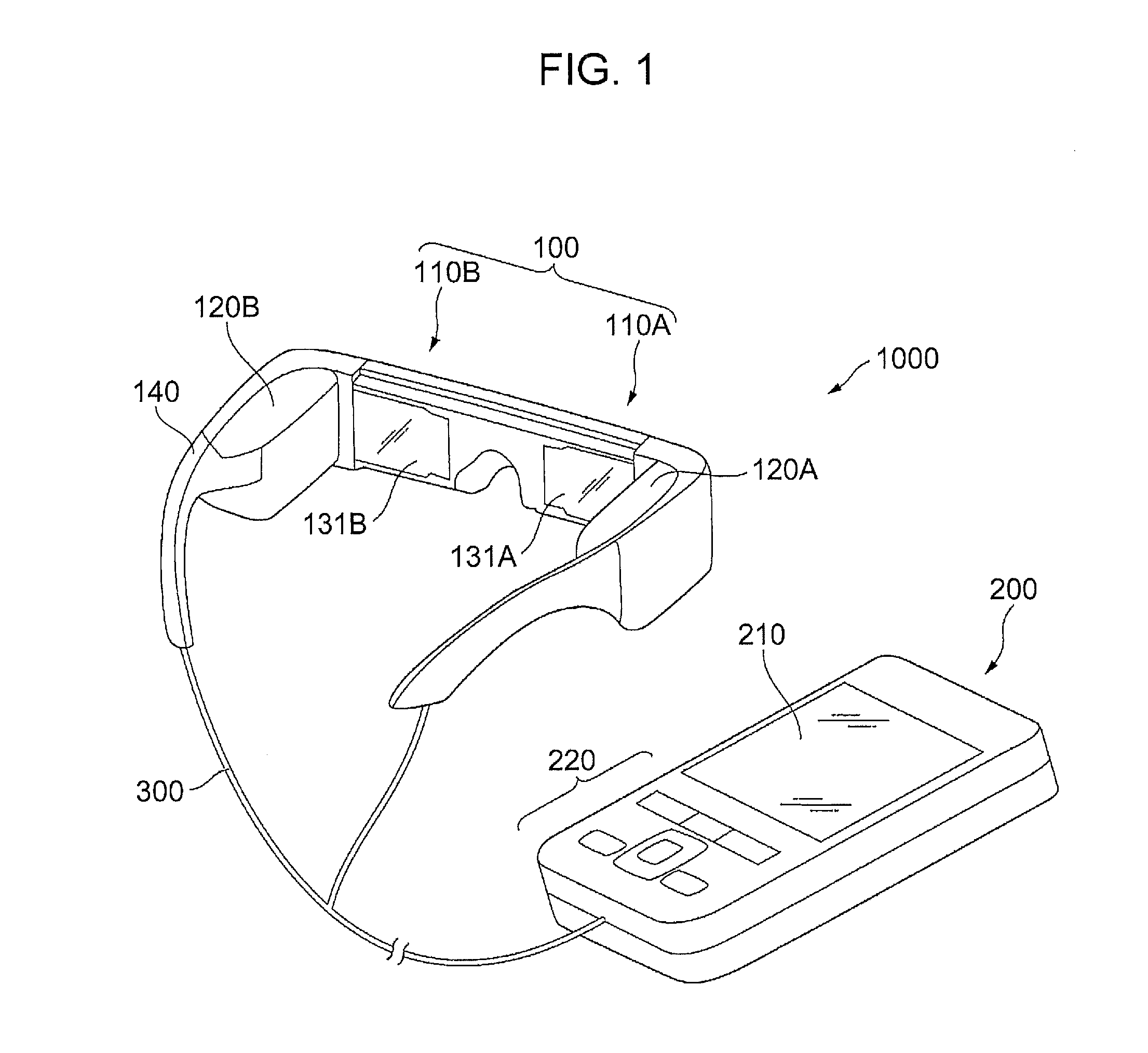
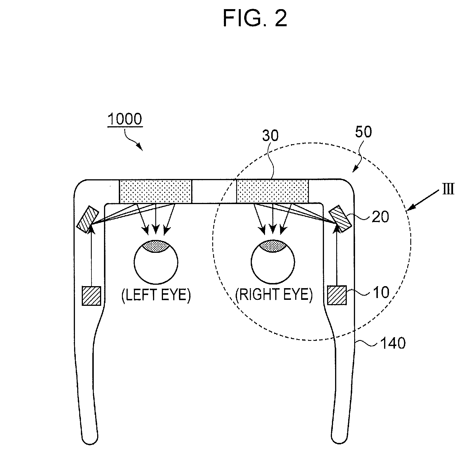
[0046]FIG. 1 is a schematic perspective view illustrating an entire image of a head mounted display (HMD) as a mounting-type image display apparatus provided with an image display apparatus. FIG. 2 is a diagrammatic plan view of the head mounted display viewed from above. Hereinafter, a configuration of the head mounted display will be described with reference to FIG. 1 and FIG. 2.

[0047]As illustrated in FIG. 1, a head mounted display 1000 includes a main body portion 100 having a shape resembling spectacles, and a control unit 200 having a size that a user can hold with his / her hand.

[0048]The main body portion 100 and the control unit 200 are connected so as to be communicable with each other via a line or radio waves. In this embodiment, the main body portion 100 and the control unit 200 are communicably connected via a cable 300. The main body portion 100 and the control unit 200 transmit an image signal and a control signal t...

second embodiment

Configuration of Image Display Apparatus

[0085]FIGS. 11A and 11B are schematic drawings illustrating a configuration of the image display apparatus of a second embodiment. FIG. 11A is a schematic plan view illustrating the image display apparatus viewed from above. FIG. 11B is a schematic side view illustrating the image display apparatus viewed from the side. FIGS. 12A and 12B are diagrammatic drawings illustrating a method of manufacturing the reflective diffraction optical element which constitutes the image display apparatus. FIG. 12A is a schematic plan view of the reflective diffraction optical element viewed from above. FIG. 12B is a schematic side view of the reflective diffraction optical element viewed from the side. Configurations of the image display apparatus and the reflective diffraction optical element, and the method of manufacturing the reflective diffraction optical element will be described with reference to FIGS. 11A and 11B and FIGS. 12A and 12B.

[0086]An image d...

third embodiment

Configuration of Image Display Apparatus

[0093]FIGS. 13A and 13B are schematic drawings illustrating a configuration of the image display apparatus of a third embodiment. The configuration of the image display apparatus will be described with reference to FIGS. 13A and 13B below.

[0094]An image display apparatus 250 of the third embodiment is different from the first embodiment described above in that a wavelength compensating element 310 as a second diffraction optical element having a function of the reflective diffraction optical element is provided on an optical path between the reflective diffraction optical element 30 and the light source 10 to cause light to enter the wavelength compensating element 310 before the scanning mirror 20, and other portions are substantially the same. Therefore, in the third embodiment, portions different from the first embodiment will be described in detail, and description of other overlapped portions is omitted as needed.

[0095]As illustrated in F...


PUM

PropertyMeasurementUnit
Heightaaaaaaaaaa
Wavelengthaaaaaaaaaa
Refractive indexaaaaaaaaaa

Abstract

An image display apparatus includes a light source configured to emit image light, a scanning mirror configured to reflect the image light from the light source, and a reflective diffraction optical element configured to change a direction of the image light from the scanning mirror to a different direction in addition to regular reflection, and the scanning mirror is arranged at a position and a height as different from an observing point as possible, and a direction of extension of an interference fringe of the reflective diffraction optical element intersects incident light from the light source.

Description

BACKGROUND[0001]1. Technical Field[0002]The invention relates to an image display apparatus and a method of manufacturing the image display apparatus.[0003]2. Related Art[0004]The image display apparatus described above is used in a head mounted display (HMD), for example, as described in International Publication No. 09 / 041055. Specifically, as illustrated in FIGS. 14A and 14B, the image display apparatus includes a light source 102 of a semiconductor laser beam or the like configured to emit light, a scanning mirror 103 configured to reflect light from the light source 102 onto a reflective diffraction optical element 104 composed of a MEMS device or the like and onto the reflective diffraction optical element 104 configured to deflect light from the scanning mirror 103 by diffraction and enables observation of the deflected light as a 1st order diffraction ray.[0005]FIG. 14A is a schematic plan view of an image display apparatus which constitutes part of the head mounted display ...

Claims


Application Information

Patent Timeline
IPC IPC(8): G02B27/01G02B26/10
CPCG02B27/0172G02B2027/0178G02B26/10G02B2027/0118G02B2027/0174
Inventor YAMADA, FUMIKA
Owner SEIKO EPSON CORP
Why Eureka
Try Eureka