3D topographic and radiological modeling of an environment

a radiological modeling and environment technology, applied in the field of 3d topographic and radiological modeling of an environment, can solve the problems that prior knowledge of a site mapping can also prove to be insufficient, and achieve the effect of improving the accuracy of the mapping

Active Publication Date: 2016-07-14
ORANO DS DEMANTELEMENT & SERVICES
View PDF1 Cites 7 Cited by
  • Summary
  • Abstract
  • Description
  • Claims
  • Application Information

AI Technical Summary

Benefits of technology

The invention provides a way to map out the exact locations of radioactive materials at a contamination site. This helps identify areas that may require cleanup or removal.

Problems solved by technology

The technical problem addressed by this patent is how to effectively model an environment that contains radioactive materials and may experience radiation contamination without requiring detailed pre-intervention maps or excessive computing resources. This applies particularly in situations where there has been limited access to the area due to changes in its topography caused by natural events like earthquakes or hurricanes.

Method used


Image

  • 3D topographic and radiological modeling of an environment
  • 3D topographic and radiological modeling of an environment
  • 3D topographic and radiological modeling of an environment

Examples


Embodiment Construction

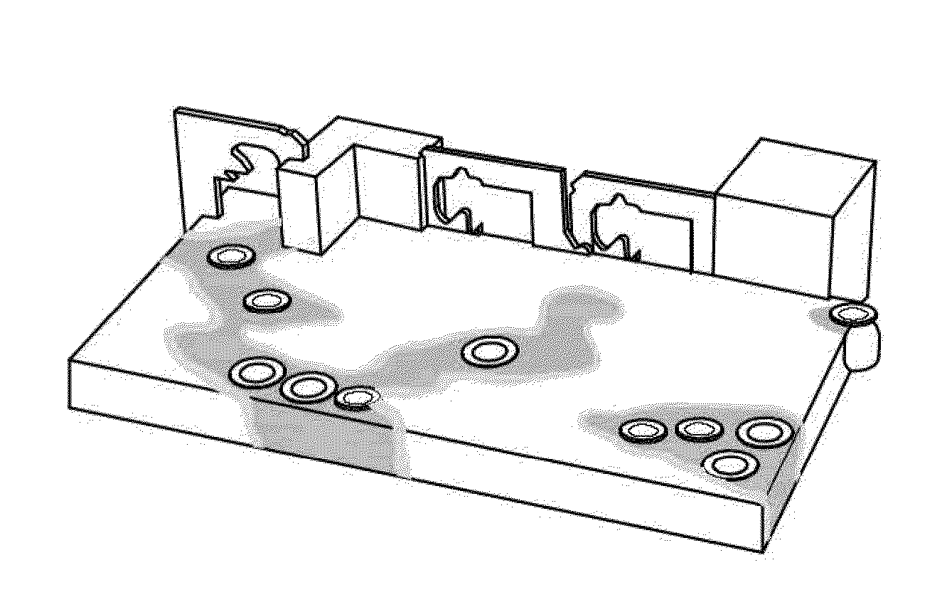
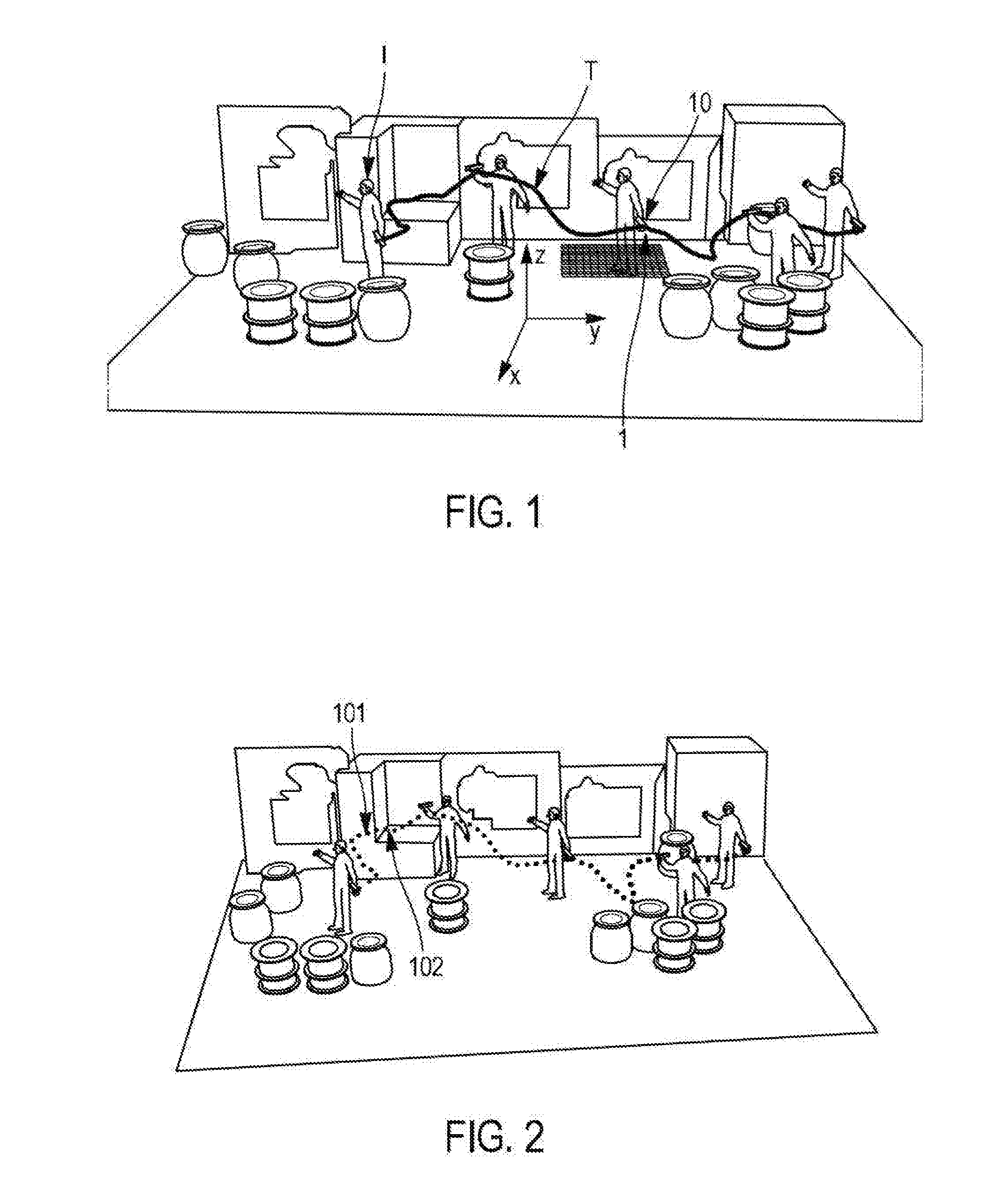
[0061]FIG. 1 illustrates an acquisition of measurements performed by an intervening operator I, displacing in a contaminated site in which there is radioactive material.

[0062]The intervening operator I uses a detection device 10 implemented according to the invention, in order to perform a modeling of this site, and to be able to implement a mapping of this site in 3 dimensions, in which topographic data and radiological data are jointly represented, and without necessarily having a prior knowledge of the topography of the site.

[0063]In this example, the detection device 10 can be integrated into a portable terminal 1 by the intervening operator I, which is displaced in the contaminated site. To enable these measurements to be obtained in 3 dimensions, besides conventional displacements on a same plane (the plane [O,x,y] of the orthogonal reference frame [O,x,y,z] given in FIG. 1), the detection device 10 is moved at different heights (defined according the axis z of the orthogonal ...


PUM


Abstract

A method for modeling an environment with a risk of nuclear contamination comprising steps of: acquiring, using a detector (10) and through a 3-dimensional displacement of the detector in the environment, information related to the topography of the environment and radiological measurement data of the environment, and then via a computer processing unit (20), associating the radiological measurement data with location data in the environment, the location data having been deduced from path data of the detector, incrementially creating, using the information and via the computer processing unit: at least one matrix in which topographic data of the environment and the radiological data associated with the location data are compiled, and a 3-dimensional mapping representing the environment in which the topographic data and the radiological data are jointly represented.

Description


Claims


Application Information

Patent Timeline
Owner ORANO DS DEMANTELEMENT & SERVICES
Why Eureka
Try Eureka