Targeted cooling in a 3D printing system

a 3d printing system and cooling technology, applied in the direction of process and machine control, instruments, computer control, etc., can solve the problems of time-consuming and difficult removal of support structures after fabrication

Inactive Publication Date: 2016-07-21
GORDON MARK CHRISTOPHER
View PDF0 Cites 53 Cited by
  • Summary
  • Abstract
  • Description
  • Claims
  • Application Information

AI Technical Summary

Problems solved by technology

Removing these support structures after fabrication can be difficult and time consuming.

Method used


Image

  • Targeted cooling in a 3D printing system
  • Targeted cooling in a 3D printing system
  • Targeted cooling in a 3D printing system

Examples


Embodiment Construction

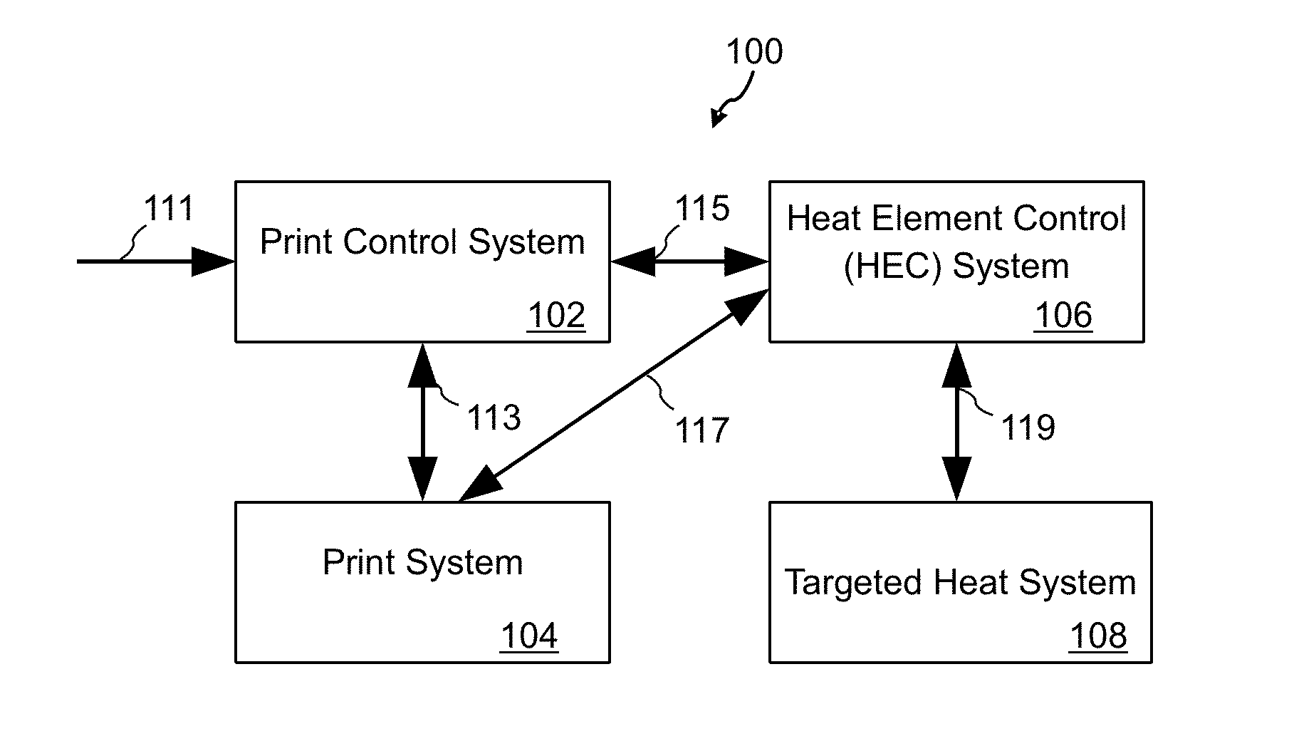
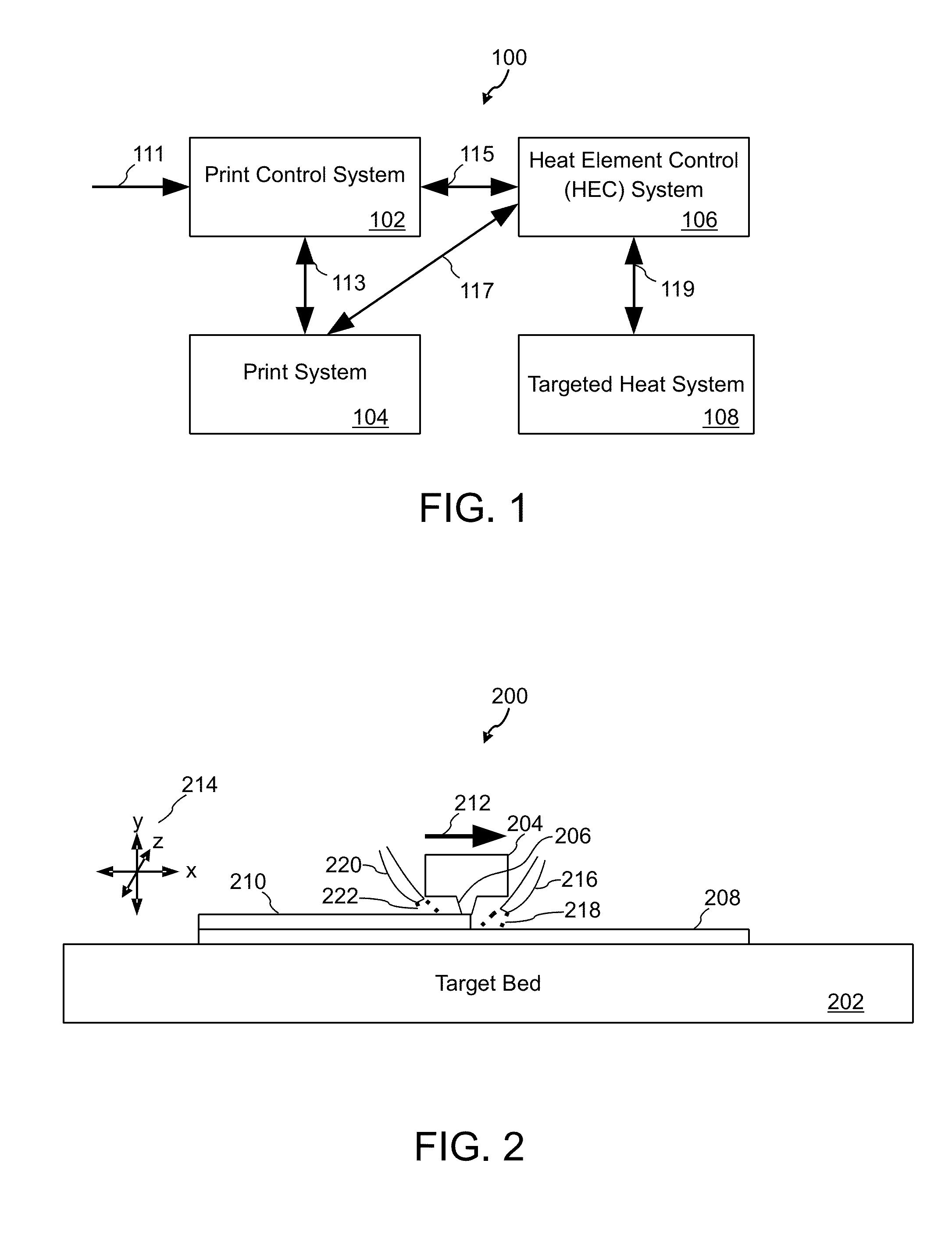
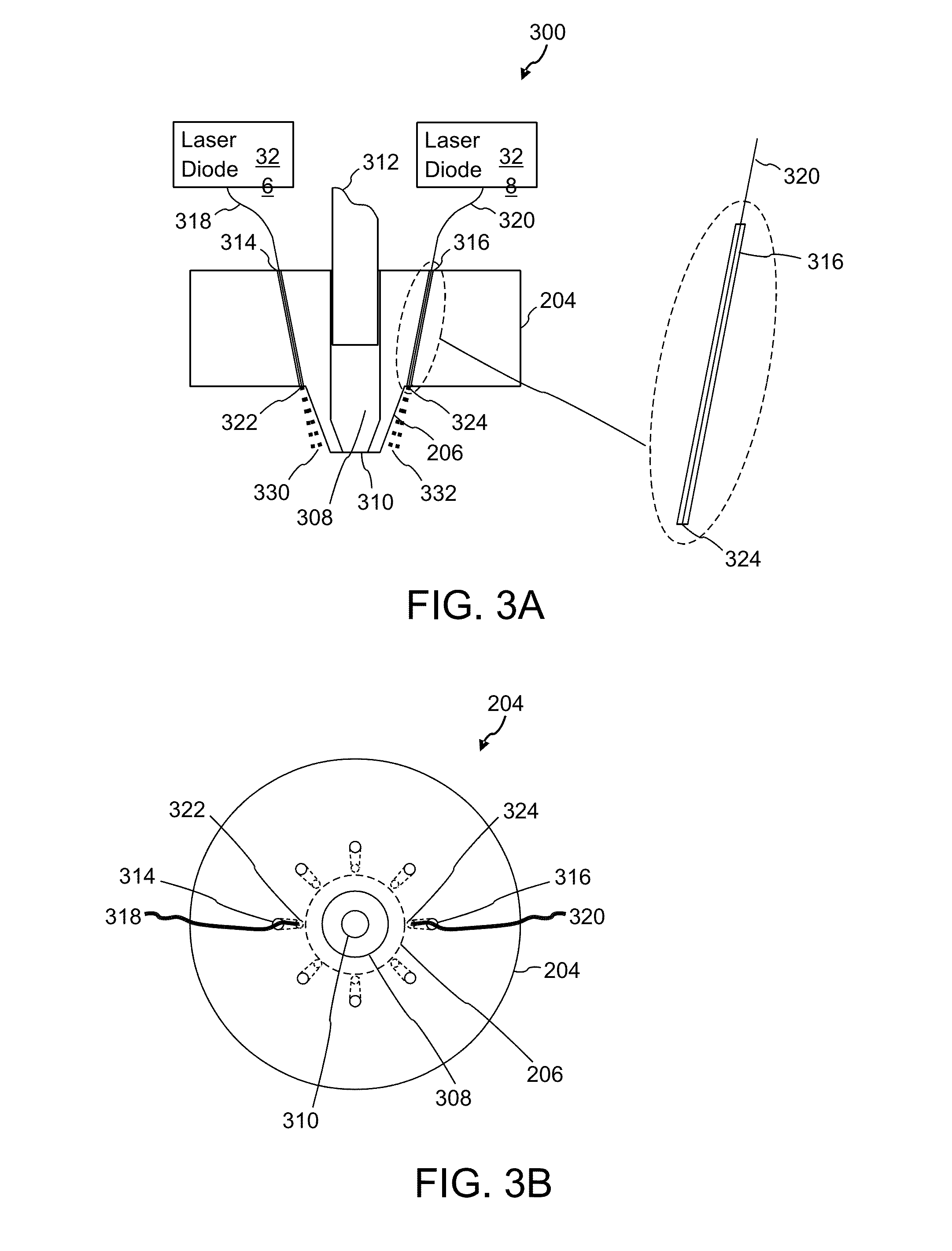
[0016]Methods, systems, and apparatuses will now be described for improving inter-layer bonding in 3D printing. Inter-layer bonding in objects manufactured by 3D printing techniques may be improved by one or more THSs (targeted heat sources) that pre-heat a targeted portion of existing object material before additional material is deposited. Properties of 3D printed objects may be improved, optimized or calibrated by pre- or post-heating a targeted area of material. One or more THSs may be attached to, integrated in, or independent of a printer in a respective 3D printing technology. THSs may be fixed, mobile, or a combination thereof to apply heat to targeted areas. For example, four fixed and equally spaced elements and 90 degree rotation provide full pre-heating coverage for a printing process. Targeted heat parameters (e.g., direction, aim, intensity, diameter or pattern of preheating) may be controlled. A THS may be integrated in or as an add-on to an existing 3D printer. A THS...


PUM

PropertyMeasurementUnit
temperatureaaaaaaaaaa
diameteraaaaaaaaaa
diameteraaaaaaaaaa

Abstract

Support structure bonding in objects manufactured by 3D printing techniques is improved by one or more targeted active cooling sources that reduce the bond strength between 3D model layers and any support structures they are in contact with. A controller may use current print layer information, current print direction or other print information to activate cooling to reduce bond strength between one or more layers. This targeted cooling enables easier removal of support structure material from a finished 3d object.

Description

CROSS-REFERENCE TO RELATED APPLICATIONS[0001]This application is a continuation in part of application Ser. No. 14 / 599,206, titled “INCREASED INTER-LAYER BONDING IN 3D PRINTING” filed on Jan. 16, 2015, the disclosure of which is incorporated herein by reference in its entirety.BACKGROUND[0002]1. Field[0003]The present invention relates to additive 3D fabrication, and, more particularly to targeted cooling in a 3D printing system.[0004]2. Description of the Related Art[0005]Three dimensional (3D) printing technologies construct or manufacture objects by printing layers of material. Categories of 3D fabrication techniques, which vary in the techniques used to create layers, include depositing extruded material, melting or sintering granular material, melting powder material, laminating layered material and polymerizing light sensitive material. Fused Filament Fabrication (FFF) is an example of a 3D printing technique that deposits layers of extruded material. Objects fabricated with F...

Claims


Application Information

Patent Timeline
Patent Type & Authority Applications(United States)
IPC IPC(8): B29C67/00G05D23/19G05B15/02
CPCB29C67/0088B33Y50/02G05D23/1917G05B15/02B33Y30/00B33Y40/00B29C64/364B33Y40/20
Inventor GORDON, MARK CHRISTOPHER
Owner GORDON MARK CHRISTOPHER
Why Eureka
Try Eureka