Winch for pipelayer and pipelayer equipped with same

Active Publication Date: 2016-07-21
KOMATSU LTD
View PDF6 Cites 15 Cited by
  • Summary
  • Abstract
  • Description
  • Claims
  • Application Information

AI Technical Summary

Benefits of technology

[0034]Thus, occurrence of uneven winding attributed to the thrust force can be suppressed by increasing the taper angle that the fleet angle becomes greater.
[0035]Accordi

Problems solved by technology

This is due to the following: in winding up the wire rope, a thrust directional force is generated and the wire rope tries to move from an end of the drum towards the middle of the drum; however, when the fleet angle is increased, the force is increased and the wire rope inappropriately moves; and thus, uneven winding is likely to be caused.
However, the aforementioned well-known method has a drawback as described below.
Moreover, in the well-known winch, when the wire rope is restrained too strongly by the aforementioned roller, the wire rope cannot move from an end of the drum towards the middle of the drum.
Hence, chances are tha

Method used


Image

  • Winch for pipelayer and pipelayer equipped with same
  • Winch for pipelayer and pipelayer equipped with same
  • Winch for pipelayer and pipelayer equipped with same

Examples


Embodiment Construction

[0055]A pipelayer according to an exemplary embodiment of the present invention will be hereinafter explained with reference to the drawings.

Schematic Structure of Pipelayer 1

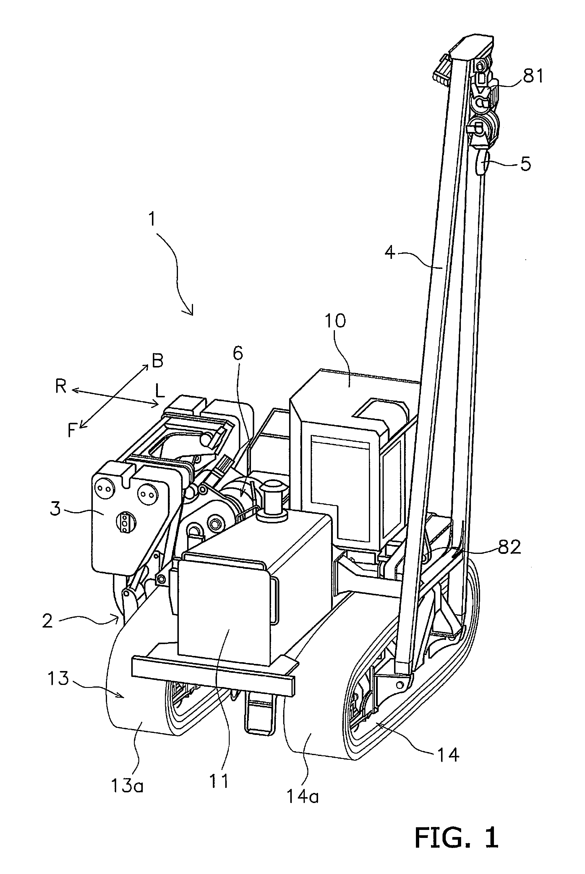
[0056]FIG. 1 is an external view of a pipelayer 1 of the present exemplary embodiment.

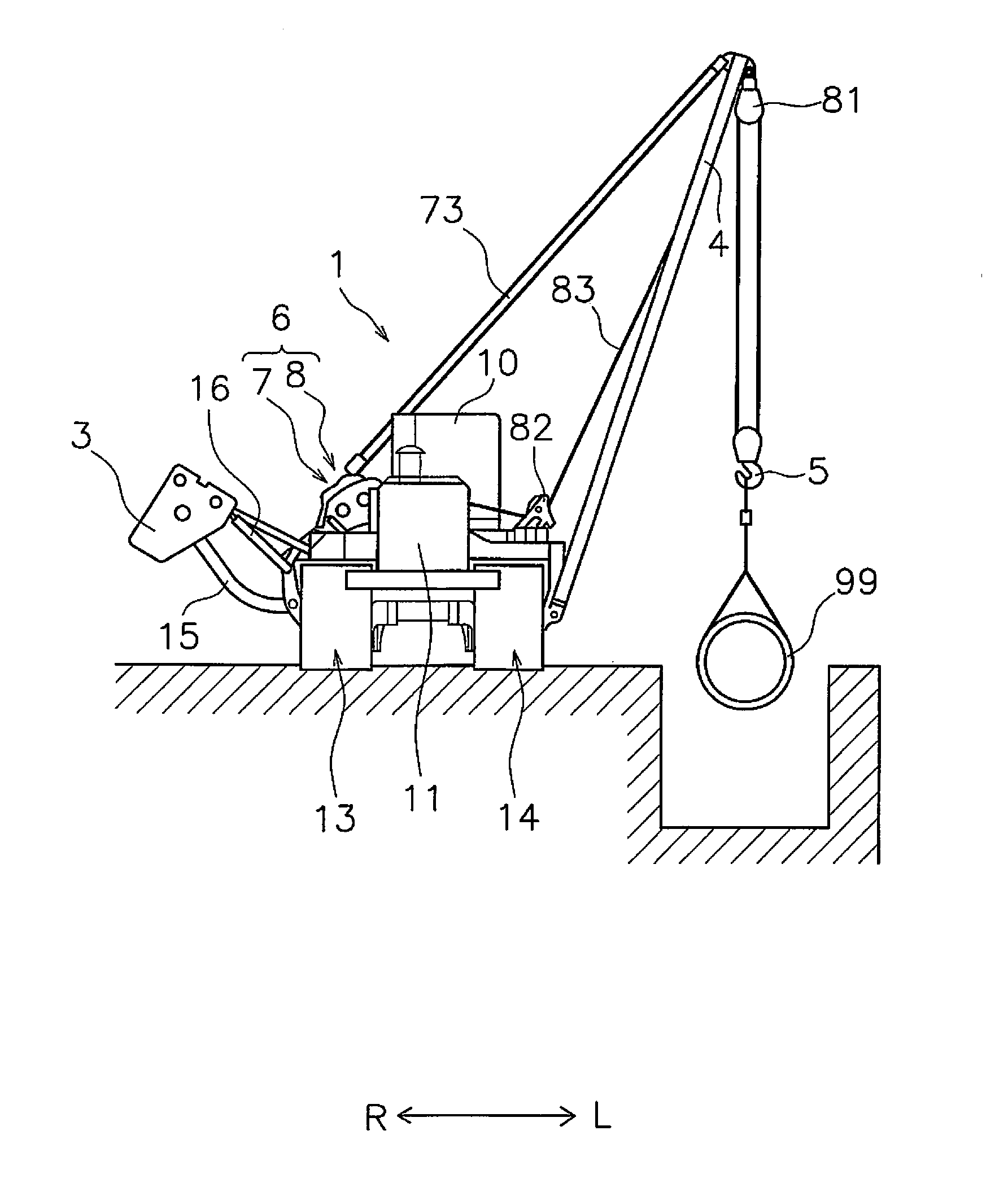
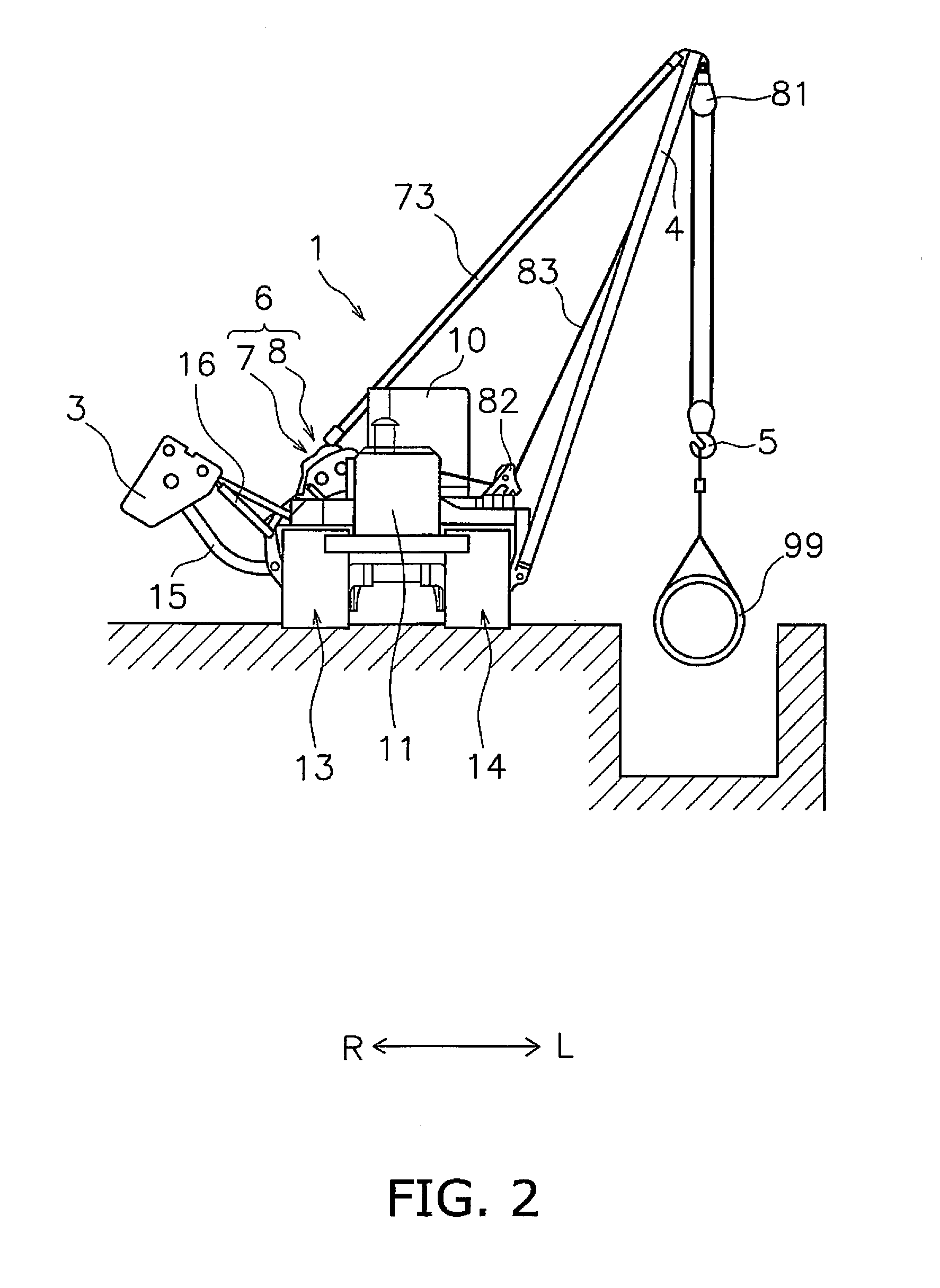
[0057]The pipelayer 1 includes a vehicle main body 2, a counterweight 3, a boom 4, a hook 5 and a winch unit 6. It should be noted that a wire rope 83 for the hook 5 (to be described) and a wire rope 73 for the boom 4 (to be described) are not illustrated in FIG. 1 for easy understanding of the drawing. Further, in the following explanation, a back-and-forth direction means the back-and-forth direction of the vehicle body seen from an operator seated in a cab 10. On the other hand, a right-and-left direction or a lateral direction means the vehicle width direction of the pipelayer 1 and corresponds to the right-and-left direction seen from the operator seated in the cab 10. Yet further, in FIG. 1, a forward direction is depict...


PUM


Abstract

A restraining roller (100) of a hook winch (8) has a roller middle part (101), a first roller end part (102) and a second roller end part (103). The roller middle part (101) is formed in a columnar shape, and each of the first roller end part (102) and the second roller end part (103) is formed in a roughly circular truncated cone shape. The widths of the first roller end part (102) and the second roller end part (103) are greater than the diameter of a wire rope (83). A difference in diameter between an inner end and outer end of each of the first and second roller end parts (102) and (103) is less than the diameter of the wire rope (83). Where a taper angle is defined as an angle formed between a line arranged in parallel to the surface of the roller middle part (101) and a line arranged in parallel to the surface of each of the first and second roller end parts (101) and (103) in a plane view seen in a direction perpendicular to a center axis of the restraining roller (100), a taper angle θ3 of the first roller end part (101) and a taper angle θ4 of the second roller end part (102) are different from each other.

Description

CROSS-REFERENCE TO RELATED APPLICATIONS[0001]This application is a U.S. National stage application of International Application No. PCT / JP2013 / 079636, filed on Oct. 31, 2013.BACKGROUND[0002]1. Field of the Invention[0003]The present invention relates to a winch for a pipelayer and a pipelayer equipped with the same.[0004]2. Background Information[0005]A pipelayer is a work vehicle for laying pipes in a construction site of pipelines for transporting oil or natural gas. Many pipelayers are tractor-based vehicles, and each is equipped with a winch and a counterweight on one width directional (transverse directional) end thereof while being equipped with a boom suspended by a wire rope released and stretched from the winch on the other width directional end thereof. In a construction site of pipelines, a plurality of pipelayers are aligned, and each lifts up a pipe by causing the winch to wind up the wire rope. The winch is coupled to a hydraulic motor and is driven by means of hydraul...

Claims


Application Information

Patent Timeline
IPC IPC(8): B66C23/44B66D1/36F16L1/028
CPCB66C23/44B66D1/36F16L1/028F16L1/065
Inventor UEMURA, TAKUYATAKEUCHI, YASUHIKOYAMAMOTO, HIROKITERAMOTO, KAZUMASA
Owner KOMATSU LTD
Why Eureka
Try Eureka