
3D printing of lead edge protective sheaths

Inactive Publication Date: 2016-07-21
HAMILTON SUNDSTRAND CORP
View PDF10 Cites 11 Cited by
  • Summary
  • Abstract
  • Description
  • Claims
  • Application Information

AI Technical Summary

Benefits of technology

The invention involves using additive manufacturing techniques to create a sheath for an airfoil component. This eliminates the need for traditional electroplating baths, which resulted in issues with the prior techniques. The sheath also features protrusions on its interior or inner side to improve its attachment to the airfoil component. Overall, this innovation simplifies the manufacturing process for airfoil components and improves their overall performance.

Problems solved by technology

Over time, the foreign object strikes may cause mechanical damage that changes the shape of the airfoil component, which is detrimental to aerodynamic efficiency, or may break it.
Airfoil components that are made of polymer composites may be particularly vulnerable to erosion because of the relatively soft nature of a polymer composite, although components made of other types of material are also vulnerable.

Method used


Image

  • 3D printing of lead edge protective sheaths
  • 3D printing of lead edge protective sheaths
  • 3D printing of lead edge protective sheaths

Examples


Embodiment Construction

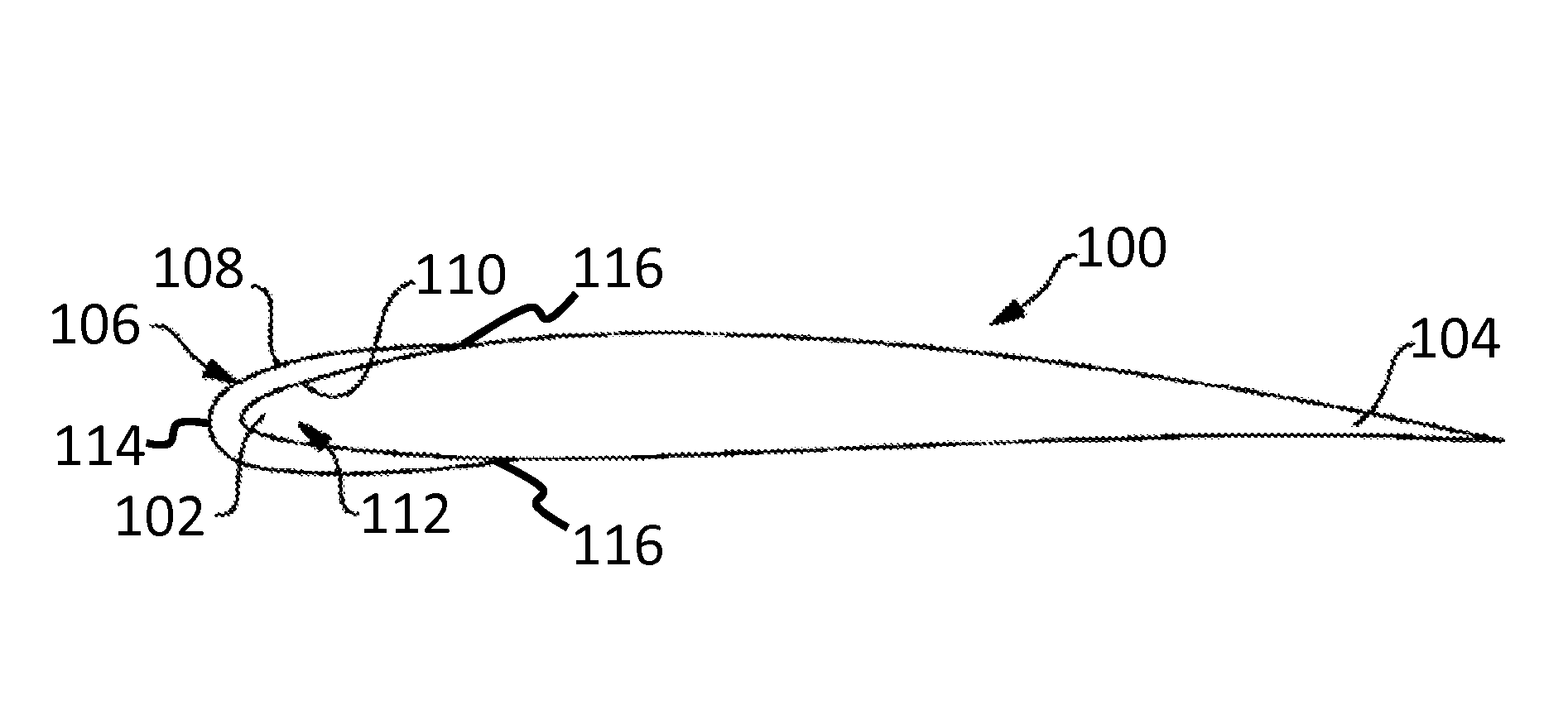
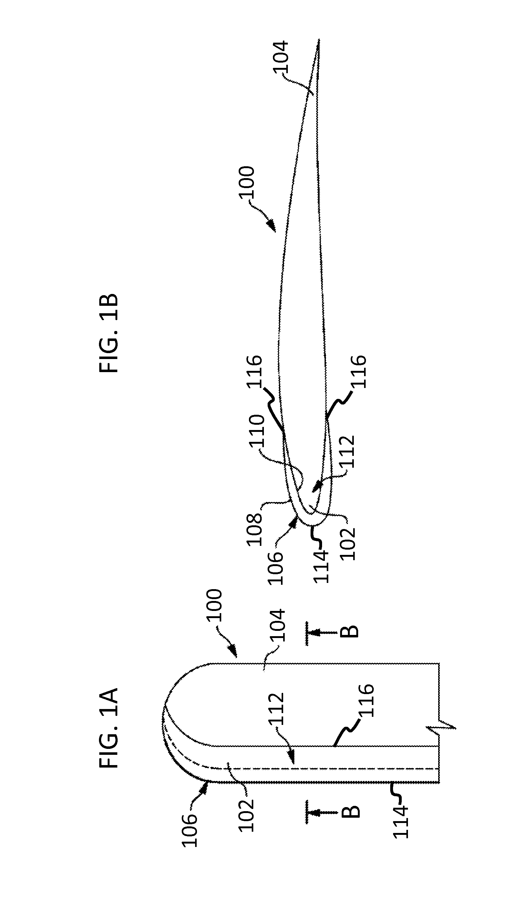
[0013]FIGS. 1A and 1B illustrate an exemplary airfoil component 100 in accordance with embodiments of the invention. Airfoil component 100 may be a propeller blade for an aircraft or wind turbine, an airfoil used within a gas turbine engine (e.g., an inlet guide vein, a compressor or turbine vein, or a compressor or turbine blade), or other type of airfoil. FIG. 1A is a top down view of the airfoil component 100, and FIG. 1B is a cross-sectional view of the airfoil component 100 as viewed along the cross-line B-B of FIG. 1A.

[0014]In the illustrated example, the airfoil component 100 includes a leading edge 102 and a trailing edge 104 relative to an air flow or expected air flow over the airfoil component 100. As will be appreciated by those of skill in the art, the airfoil component100 may be made of any of a variety of different types of materials, for example, including but not limited to, a metallic alloy and / or a polymer composite. In operation, the airfoil component 100, and pa...


PUM


Abstract

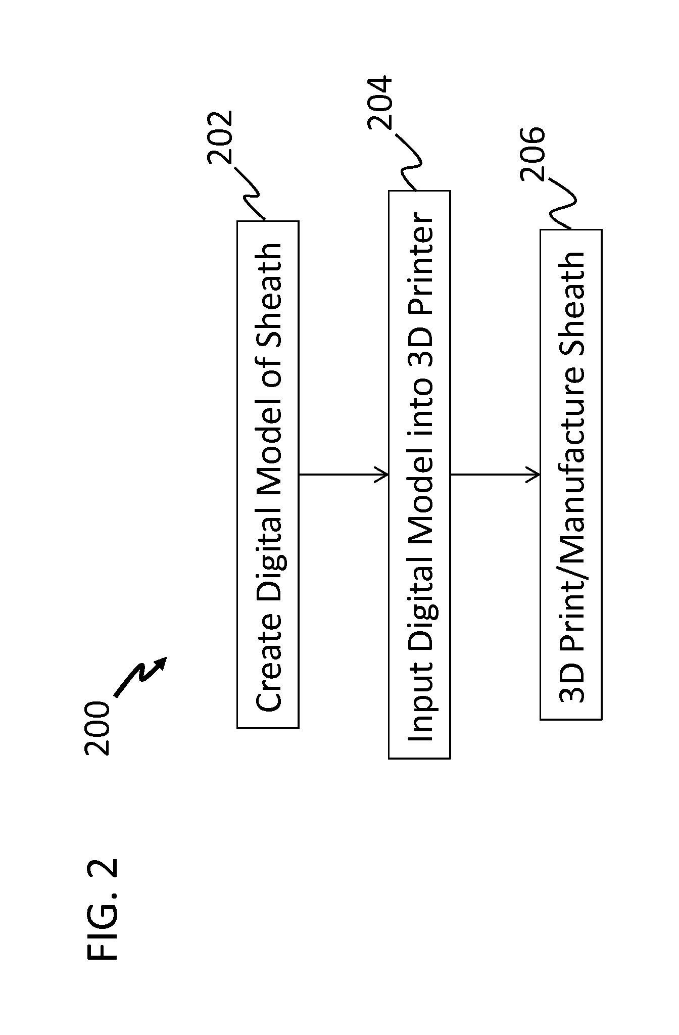
A method of manufacturing a lead edge protective sheath for an airfoil component is provided. The method includes generating a digital model of a lead edge protective sheath for an airfoil component, inputting the digital model into an additive manufacturing machine, and printing, with one or more selected materials, a lead edge protective sheath for an airfoil component based on the digital model.

Description

BACKGROUND OF THE INVENTION[0001]This subject matter disclosed herein generally relates to protective sheaths and, more particularly, to a protective sheath that is 3D printed for improving resistance to erosion of propeller blades, vanes, turbine blades, or other airfoil components.[0002]Airfoil-shaped components are used in various types of aircraft for propeller blades and engine components such as vanes and blades, and outside of the aircraft industry airfoil-shaped components may be used in fans, turbines, or other devices. Particularly in the aircraft industry, but not limited thereto, the airfoil components are typically located within an air stream that may include foreign objects such as sand, ice, water droplets, stones, birds, or other debris. The foreign objects may strike or impact the airfoil component, particularly at a leading edge of the airfoil component. Over time, the foreign object strikes may cause mechanical damage that changes the shape of the airfoil compone...

Claims


Application Information

Patent Timeline
IPC IPC(8): F01D5/28B22F7/08B22F3/105
CPCF01D5/28B22F3/1055B22F7/08B33Y10/00F05D2230/31F05D2240/30F05D2240/12F05D2220/30F01D5/147B22F5/04F01D5/14F01D5/141F04D29/324F05D2230/22F05D2230/30F05D2240/303Y02P10/25Y02T50/60B33Y80/00B22F10/28
Inventor SMITH, BLAIR A.
Owner HAMILTON SUNDSTRAND CORP
Learn More