Modular precision drill countersink assembly

a countersink and drill bit technology, applied in the field of drill bits, can solve the problems of high abrasion of cfrp and rapid wear of the cutting edges of the countersink portion of the drill bit currently used, and achieve the effect of greater precision

Active Publication Date: 2013-06-25
PRECORP INC
View PDF14 Cites 7 Cited by
  • Summary
  • Abstract
  • Description
  • Claims
  • Application Information

AI Technical Summary

Benefits of technology

[0006]In accordance with the present invention, there is provided a modular cutting tool assembly whereby a hole of greater precision can be created with an improved match between the fastener and the recess created by the cutting tool assembly. Such an improved match is very beneficial for positioning of an aircraft fastener flush with the skin of an aircraft structure.

Problems solved by technology

CFRP is highly abrasive and creates rapid wear on the cutting edges of the drill and countersink portion of tools presently used in this material.

Method used


Image

  • Modular precision drill countersink assembly
  • Modular precision drill countersink assembly
  • Modular precision drill countersink assembly

Examples


Embodiment Construction

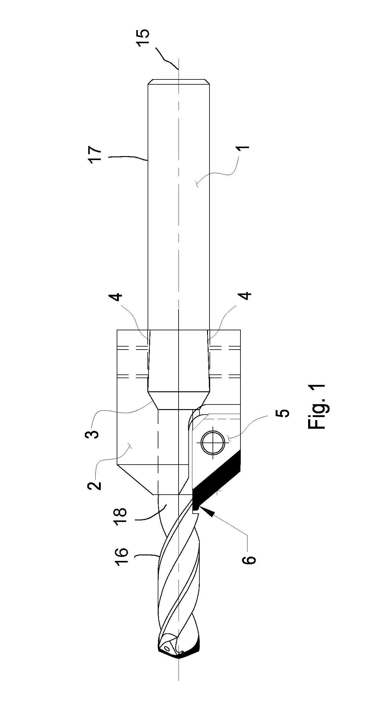
[0019]FIG. 1 illustrates the cutting tool assembly according to the invention with drill 1, body 2, and insert 5. Drill 1 and the body 2 have matching tapered surfaces 3 that, combined with tapered flat surfaces 4, provide for the precise location of radius cutting edge 6 both axially and radially to the centerline 15 of drill 1.

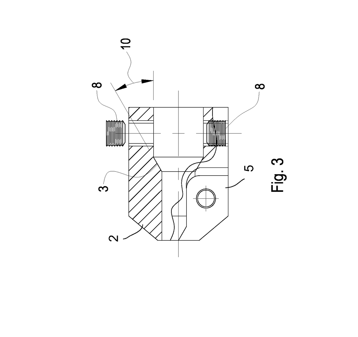
[0020]FIG. 3 illustrates the body 2 of the cutting tool assembly showing angle 10 that provides the tapered surface 3 that is used to create the precise location of the body 2 to drill 1. The taper mating of these two parts of the assembly greatly improves the precision of the location of the insert 5 (shown in FIG. 4) to the assembly.

[0021]FIG. 5 shows opposing flat surfaces 4 which have a slight backtaper of angle 12 on drill shank 17. When the set screws 8 (see FIG. 3) are tighten against flat surfaces 4, the body 2 is pulled against the mating tapered surface 3 such that the body 2 is precisely and rigidly positioned together with drill 1 such that the c...


PUM

PropertyMeasurementUnit
radiusaaaaaaaaaa
strengthaaaaaaaaaa
angleaaaaaaaaaa

Abstract

A modular countersink assembly, comprising a drill having an exterior tapered surface, a countersink body having an interior tapered surface for mating with the exterior tapered surface of the drill, and an insert removably secured to the countersink body enables an operator to replace either the drill and/or the insert if one or the other or both become worn. The insert is positioned both axially and radially and may have a PCD cutting edge.

Description

TECHNICAL FIELD[0001]The present invention relates generally to drill assemblies. More specifically, the present invention relates to modular drill assemblies requiring high precision as used for aircraft fasteners for example.BACKGROUND[0002]This invention relates to a drill countersink assembly for accurately preparing precision holes in materials for fasteners, specially for aircraft fasteners used to attach aircraft skins to the frame of the aircraft or wing assembly where such fasteners need to fit precisely into the material to provide the optimum strength of the bonded structure and to avoid mismatches that would allow the head of the fastener to be either above or below the skin and thereby increase the drag on the surface of the plane. In particular, this invention is concerned with the ability to accurately match the precise form of the fastener head, matching the angle of the fastener head and fillet radius, so that when positioned in the hole, the fastener head is as per...

Claims


Application Information

Patent Timeline
Patent Type & Authority Patents(United States)
IPC IPC(8): B23B51/08
CPCB23B51/108B23B2251/50Y10T408/9065Y10T408/87Y10T408/62Y10T408/81
Inventor GARRICK, RICHARD M.BUNTING, JOHN A.PREECE, DAVID J.
Owner PRECORP INC
Why Eureka
Try Eureka