
Lighting device attachment for mobile devices

a technology for mobile devices and light sources, which is applied in the direction of lighting and heating equipment, instruments, machine supports, etc., can solve the problems of increasing the cost of flashlights, difficult to control texturing on optical outputs, and poor beam quality of paraboloidal reflectors, so as to reduce the drain of batteries and high-quality imagery

Inactive Publication Date: 2016-07-21
SUREFIRE LLC
View PDF2 Cites 18 Cited by
  • Summary
  • Abstract
  • Description
  • Claims
  • Application Information

AI Technical Summary

Benefits of technology

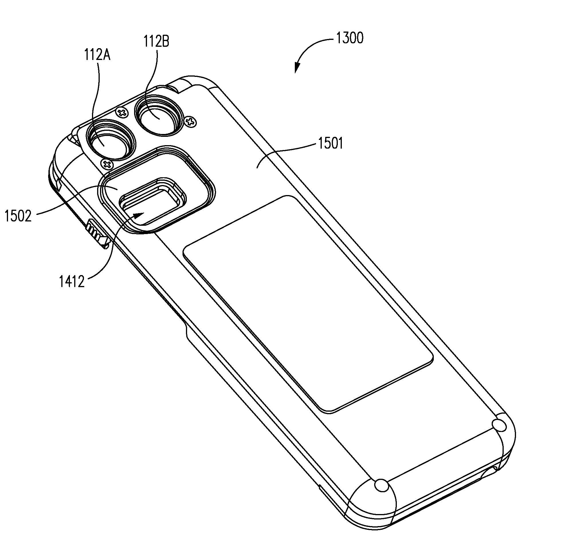
The patent text describes an illumination device that can be attached to a mobile device and produce a high-quality beam of light for still or video images. The device uses multiple light sources that emit light along different optical axes to create a non-symmetrical beam. The device also has undulations on its internal surface to smooth the light beam and create a more uniform image. Additionally, the device can adjust the intensity of the light beams to create the desired beam shape and reduce drain on the battery. Overall, this illumination device is superior to existing flash or illumination devices in mobile devices.

Problems solved by technology

However, the surround-beam intensity outside the central collimated portion of beams produced by paraboloidal reflective optics is typically lower than would be preferred by most users, even for viewing objects at relatively short ranges.
In addition, the beam quality (i.e., beam smoothness) produced by a paraboloidal reflector is often poor in the central collimated region due to imaging of various structures in the light source.
The effect of such texturing on the optical output is difficult to control, so considerable trial and error in spraying the droplets is often required to achieve satisfactory results.
However, this increases the cost of the flashlight and reduces the light output due to Fresnel reflection.
However, in many cases reducing the focal length can be difficult or impossible due to the need to avoid a reflective surface that is impractically close to the light source and prevents providing sufficient space for the light source to be mounted with adequate clearance.
The ever-present consumer demand for lighter and smaller devices and for longer battery life in the devices poses a challenge to provide light sources in mobile devices that provide sufficient illumination, illumination of a desirable color, and / or illumination with an effective beam shape for image capture and other scene illumination purposes without creating undesirably bulky or power hungry devices.
The built-in illuminators in current mobile devices generally provide inadequate illumination under low-ambient-lighting conditions for still photography and, especially, for videography at substantially longer image-capture ranges (e.g., up to 50 feet).
Even for scenes illuminated by moderate to high levels of ambient light, these built-in illuminators often fail to provide adequate supplemental illumination to reduce image contrast to acceptable levels when there are large differences in the level of ambient illumination between different regions within a scene to be imaged (e.g., a person standing in a shaded area with a light-colored, sun-illuminated building in the background).
Due to constraints on weight, volume, shape (e.g., thickness), and available electrical power, it is difficult to incorporate into a given mobile device a built-in illuminator that provides adequate performance over a wide range of commonly encountered ambient lighting conditions, particularly in the case of small mobile devices such as mobile phones, and also particularly for videography.
The built-in illuminators in most current mobile devices have no capability for adjustment of the color temperature.
The light projected by an illuminator outside the camera's FOV does not contribute to illuminating the scene being captured and represents a waste of energy.

Method used


Image

  • Lighting device attachment for mobile devices
  • Lighting device attachment for mobile devices
  • Lighting device attachment for mobile devices

Examples


case 5100

[0276]Case 5100 also includes a wedge-shaped locking member 5116 having a contact surface 5118 configured to engage with a complementary feature of illumination device 6000 as further described herein.

[0277]Case 5100 includes textured surfaces 5130 adjacent to ribs 5124. Outer surface 5132 includes textured surfaces 5128 (e.g., in a dimpled pattern as shown or otherwise). In various embodiments, textured surfaces 5128 and / or 5130 may be provided to permit a user to conveniently grip case 5100 while illumination device 6000 is attached thereto.

[0278]FIGS. 60-63 are various views of illumination device 6000 illustrating mechanical structures used to attach it to mobile device 5900 through case 5100 in accordance with embodiments of the disclosure. FIG. 64 is a cross-sectional view of case 5100, mobile device 5900, and illumination device 6000 in accordance with embodiments of the disclosure. FIGS. 65-67 are various views of illumination device 6000 in a process of engagement with case...


PUM


Abstract

A lighting device attachment for a mobile device may include a housing that defines a cavity or an external coupling member configured to receive the mobile device, a light source within the housing, and an optical element adapted to project light from the light source to illuminate an external scene. The attachment may include multiple light sources and multiple associated optical elements to generate a combined beam for illuminating the external scene which may include the field of view of a camera of the mobile device. The camera and the light sources may be cooperated to capture still or video images. The attachment may include a battery that provides power to the light sources and / or the mobile device and may charge a battery of the mobile device. The light sources may be operated by a control device of the attachment and / or by the mobile device. Related methods are provided.

Description

CROSS-REFERENCE TO RELATED APPLICATIONS[0001]This application claims priority to and the benefit of U.S. Provisional Patent Application No. 62 / 104,038 filed Jan. 15, 2015 and entitled “LIGHTING DEVICE WITH REFLECTIVE NON-PARABOLOIDAL BEAM-SHAPING OPTICS AND LIGHTING DEVICE ATTACHMENT FOR MOBILE DEVICES” which is hereby incorporated by reference in its entirety.[0002]This application claims priority to and the benefit of U.S. Provisional Patent Application No. 62 / 169,491 filed Jun. 1, 2015 and entitled “ILLUMINATION DEVICE FOR PERFORMING VIDEOGRAPHY AND PHOTOGRAPHY WITH MOBILE DEVICES” which is hereby incorporated by reference in its entirety.[0003]This application is related to U.S. patent application Ser. No. 14 / 996,135 filed Jan. 14, 2016 and entitled “REFLECTIVE NON-PARABOLOIDAL BEAM-SHAPING OPTICS” which is hereby incorporated by reference in its entirety.[0004]This application is related to U.S. patent application Ser. No. 14 / 996,152 filed Jan. 14, 2016 and entitled “ILLUMINATI...

Claims


Application Information

Patent Timeline
Patent Type & Authority Applications(United States)
IPC IPC(8): F21V33/00H04M1/02F21V17/10G03B15/05F21L4/04F21V7/00
CPCF21V33/0052F21L4/04H04M1/0254F21V17/104G03B15/05F21V7/0075F16M11/041H04M1/21G03B2215/0517G03B2215/056H04M1/04H04M1/22G03B2215/0514F16M13/00F16M13/022
Inventor MATTHEWS, JOHN W.NGUYEN, LOCSOO, ALEXPICCIOTTA, MICHAEL D.SHATZ, NARKISBORTZ, JOHN C.
Owner SUREFIRE LLC
Learn More