Voice Coil Actuator with Integrated LVDT

a voice coil actuator and voice coil technology, applied in the direction of dynamo-electric components, dynamo-electric machines, instruments, etc., can solve the problems of not having position feedback sensing capabilities and operating too slowly for most applications, and achieve accurate armature position sensing and rapid and accurate focus through the lens

Active Publication Date: 2016-07-21
MAGNET SCHULTZ OF AMERICA
View PDF0 Cites 4 Cited by
  • Summary
  • Abstract
  • Description
  • Claims
  • Application Information

AI Technical Summary

Benefits of technology

[0003]In the past, stepping motors have been used to position a lens barrel and associated lens in medical positioning apparatus. The problem with a stepping motor with position feedback is that is operates too slowly for most applications. Applicant's invention replaces a stepping motor with a voice coil actuator with integrated position sensing. The voice coil allows for a faster response and thus shorter equipment use time when performing a procedure.
[0005]Typical Linear Voltage Displacement Transducers (“LVDT”) have a means to alter the position of the magnetic core. The LVDT converts rectilinear motion of an object to which it is coupled mechanically into a corresponding electrical signal. LVDT linear position sensors can very accurately measure movements as small as a few millionths of an inch up to several inches. The moving element of an LVDT is a separate tube, which is free to move axially in the LVDT's hollow bore and is mechanically coupled to the object whose position is being measured.
[0007]Applicant's invention places a voice coil adjacent to and in linear alignment with an LVDT sensor. The voice coil provides accurate armature position sensing. The voice coil actuator has a moving magnet armature which contains the magnetic core required for the LVDT. Applicant provides a hole through the center of the voice coil and LVDT to allow a laser beam to pass through the voice coil and LVDT. There is a core tube or moving armature that passes through the voice coil and LVDT and which has a lens adapter and lens at one end. By accurately moving and positioning the moving armature, the laser beam can be quickly and accurately focused through the lens.BRIEF DESCRIPTION OF THE DRAWINGS

Problems solved by technology

The problem with a stepping motor with position feedback is that is operates too slowly for most applications.
Generally voice coil actuators do not have position feedback sensing capabilities.

Method used


Image

  • Voice Coil Actuator with Integrated LVDT
  • Voice Coil Actuator with Integrated LVDT
  • Voice Coil Actuator with Integrated LVDT

Examples


Embodiment Construction

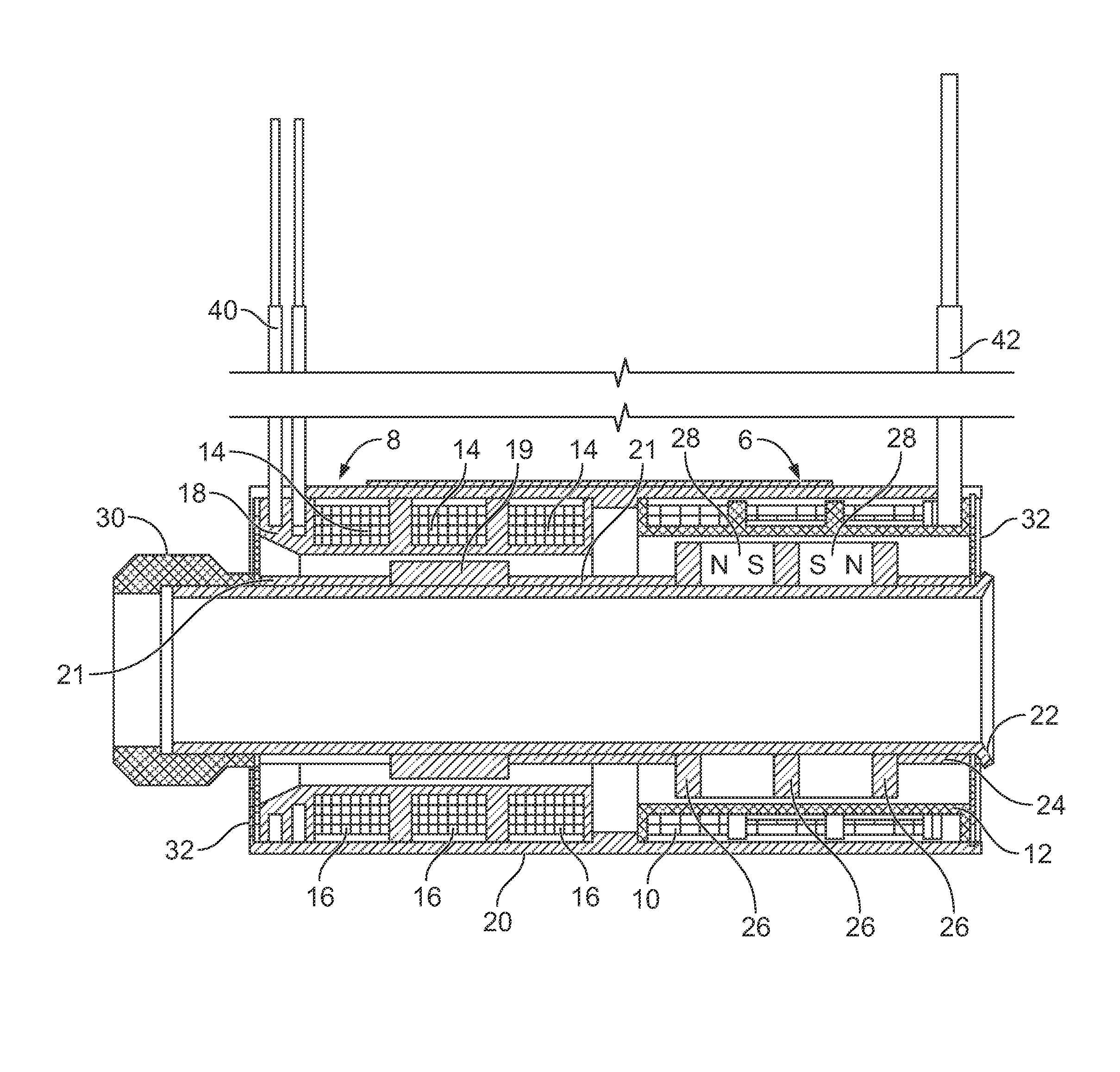
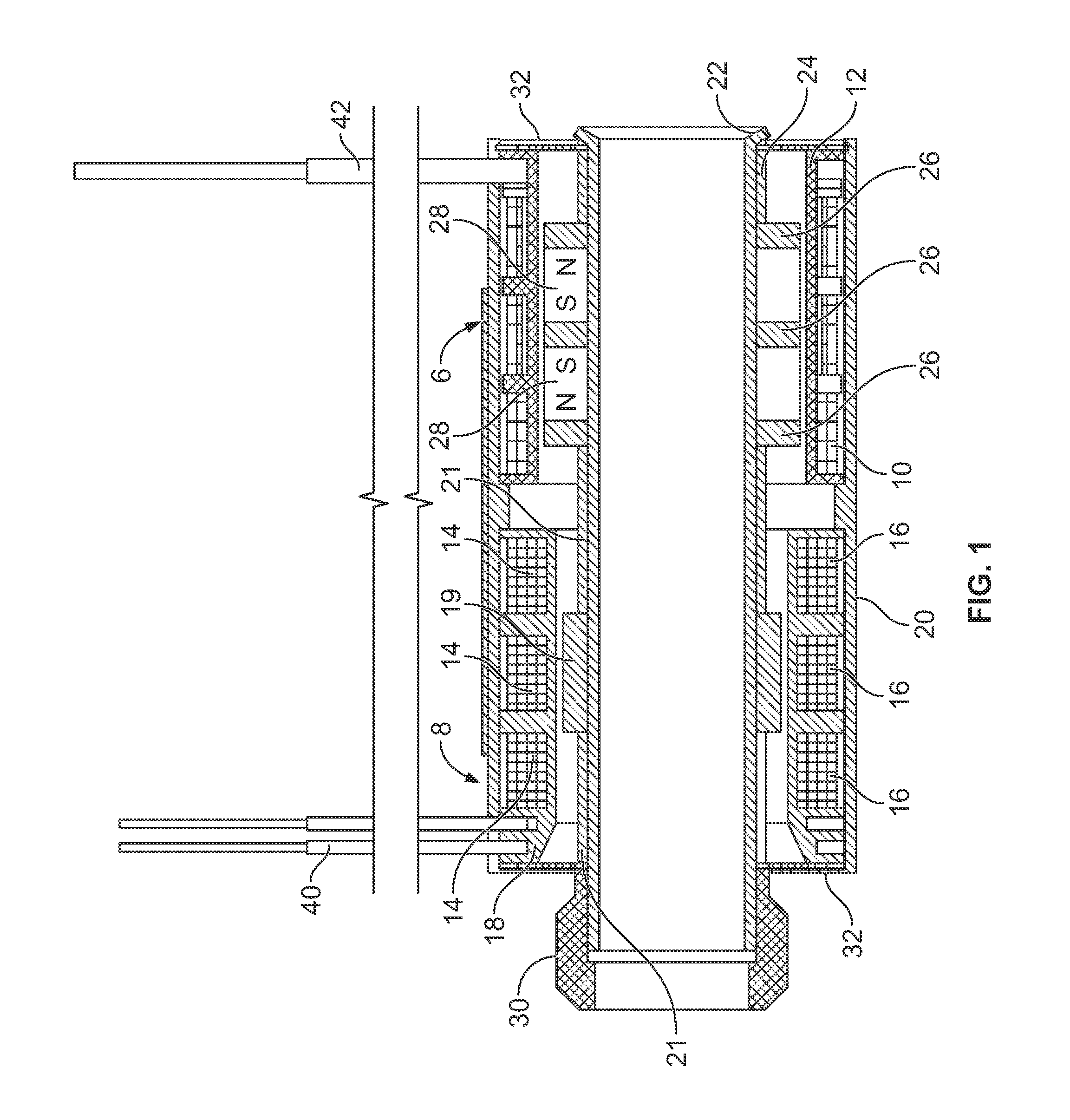
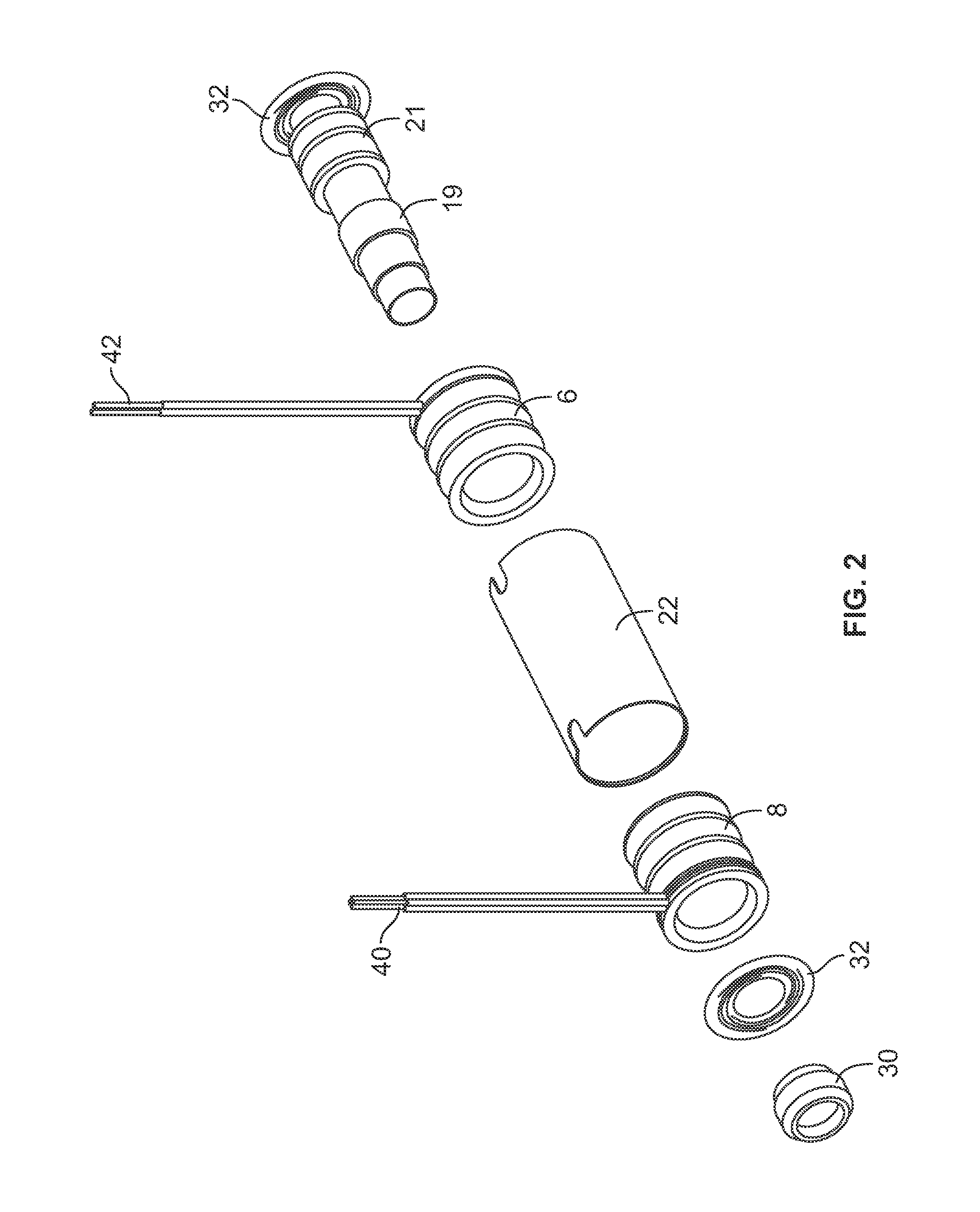
[0010]Turning first to FIG. 1 there are a voice coil 6 and a linear voltage displacement transducer (referred to herein as “LVDT”) sensor 8. As seen, these two devices are mounted together as a singular device. There are voice coil windings 10 with multiple coils windings in opposite winding directions for the voice coil 6 which are wound over a voice coil bobbin 12. There are LVDT primary windings 14 wound in the center of the LVDT bobbin 18 and the LVDT secondary windings 16 wound on the outside ends of the LVDT bobbin 18. There is a LVDT core 19 and non magnetic spacers 21 around the LVDT bobbin 18. The LVDT primary windings 14 and secondary windings 16 are housed in a ferromagnetic housing 20.

[0011]The voice coil 6 is comprised of a moving armature assembly 21 which consists of a unitary piece non-magnetic core tube 22, which may be made of brass, non-magnetic spacers 24, which also may be made of brass, multiple ferromagnetic armatures 26, and multiple permanent magnets 28 in o...


PUM


Abstract

A device for focusing a laser in which a voice coil and LVDT are mounted in parallel alignment with each other and have a common centrally disposed armature. A central bore extends through the armature. A lens is mounted at one end of the armature and a laser is located at the opposite end. The laser beam passes through the central bore and is focused by the voice coil moving the armature which in turn moves the lens. The LVDT accurately positions the armature to focus the laser beam.

Description

CROSS REFERENCE TO RELATED APPLICATION[0001]This application claims priority of provisional patent application Ser. No. 61 / 933,374 filed Jan. 30, 2014.FIELD OF THE INVENTION[0002]This invention relates to a voice coil actuator with a position feedback sensing capability to accurately position a lens mounted on a moveable tube.BACKGROUND AND SUMMARY OF THE INVENTION[0003]In the past, stepping motors have been used to position a lens barrel and associated lens in medical positioning apparatus. The problem with a stepping motor with position feedback is that is operates too slowly for most applications. Applicant's invention replaces a stepping motor with a voice coil actuator with integrated position sensing. The voice coil allows for a faster response and thus shorter equipment use time when performing a procedure.[0004]Generally voice coil actuators do not have position feedback sensing capabilities. Voice coil actuators are generally available in either the moving magnet or moving ...

Claims


Application Information

Patent Timeline
Patent Type & Authority Applications(United States)
IPC IPC(8): G02B7/08H02K41/02
CPCH02K41/02G02B7/08H02K41/0356H02K11/225
Inventor CODE, KEVIN
Owner MAGNET SCHULTZ OF AMERICA
Why Eureka
Try Eureka