Visual Localization Within LIDAR Maps

Active Publication Date: 2016-07-21
RGT UNIV OF MICHIGAN
View PDF4 Cites 85 Cited by
  • Summary
  • Abstract
  • Description
  • Claims
  • Application Information

AI Technical Summary

Benefits of technology

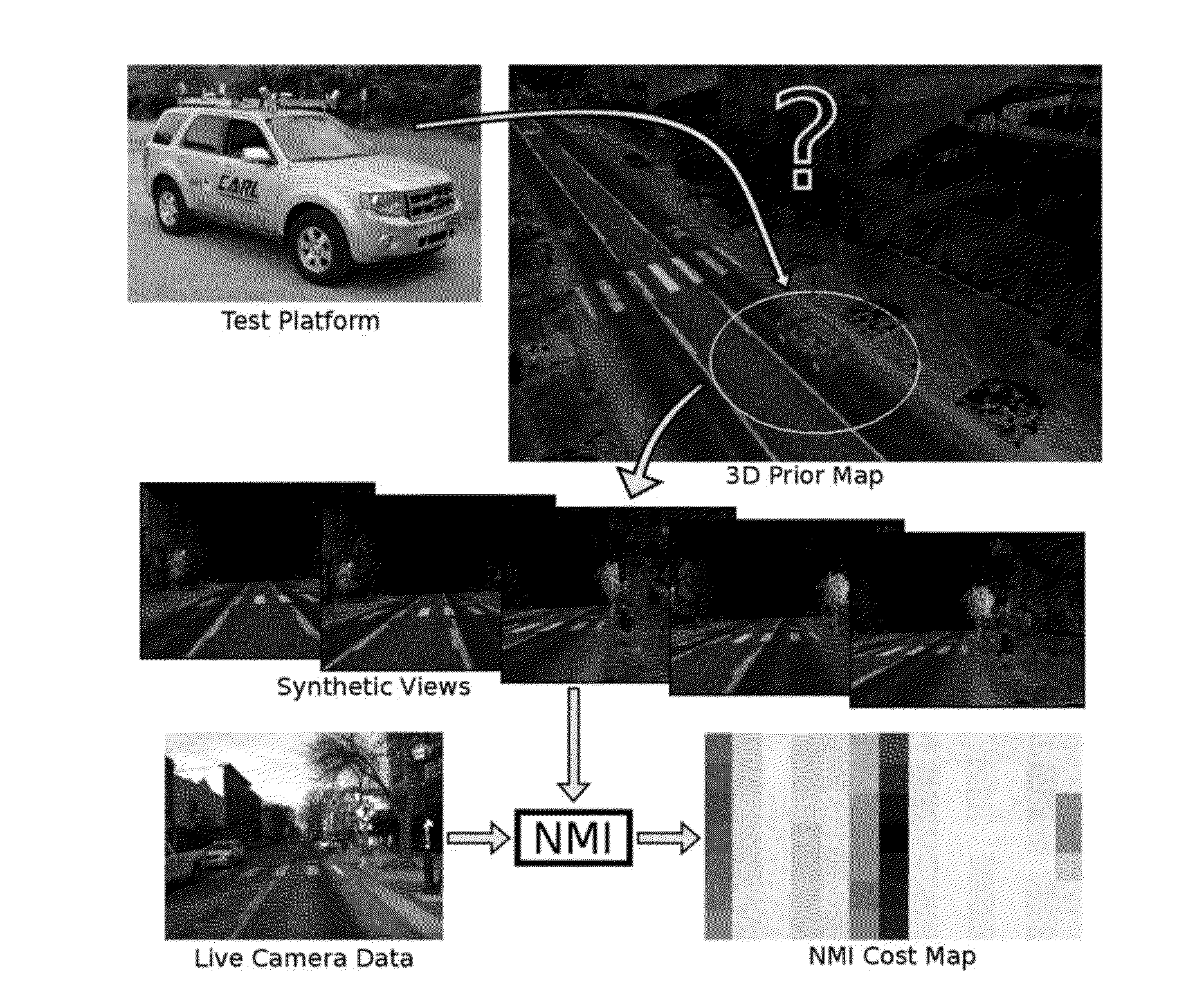
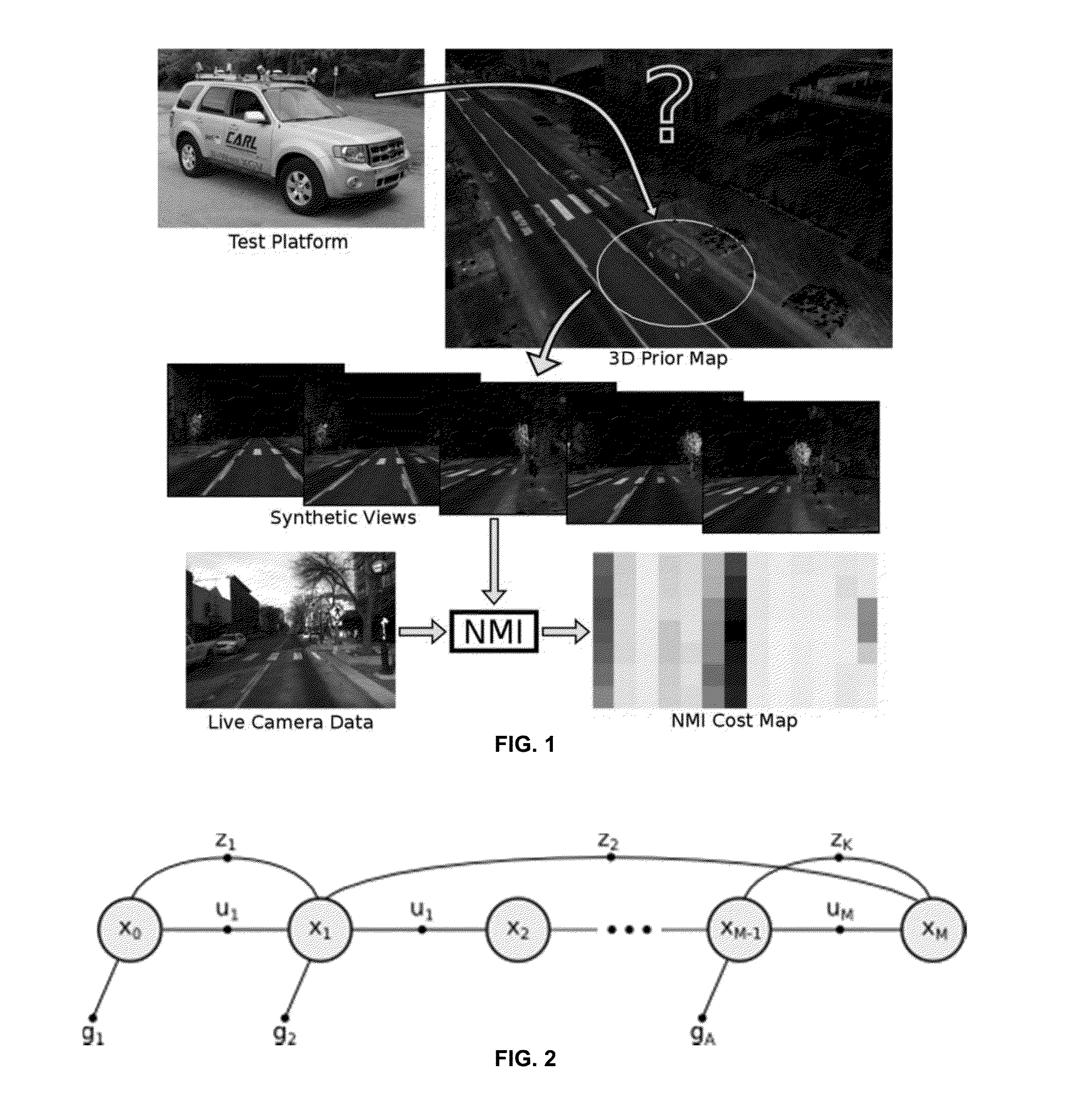
[0040]In work by Stewart and Newman, the use of a 3D map for featureless camera-based localization that exploits the 3D structure of the environment was explored. They were able to localize a monocular camera by minimizing normalized information distance between the appearance of 3D LIDAR points projected into multiple camera views. Further, McManus et al. used a similar 3D map with reflectivity information to generate synthetic views for visual distraction suppression.
[0041]This approach has been previously considered, but methods thus far rely on the reconstruction of the local ground plane from a stereo camera pair. Senlet and Elgammal create a local top-view

Problems solved by technology

Rather than using the vehicle's sensors to explicitly perceive lane markings, traffic signs, etc., metadata is embedded into a prior map, which t

Method used


Image

  • Visual Localization Within LIDAR Maps
  • Visual Localization Within LIDAR Maps
  • Visual Localization Within LIDAR Maps

Examples


Embodiment Construction

[0027]Example embodiments will now be described more fully with reference to the accompanying drawings.

[0028]Example embodiments are provided so that this disclosure will be thorough, and will fully convey the scope to those who are skilled in the art. Numerous specific details are set forth such as examples of specific components, devices, and methods, to provide a thorough understanding of embodiments of the present disclosure. It will be apparent to those skilled in the art that specific details need not be employed, that example embodiments may be embodied in many different forms and that neither should be construed to limit the scope of the disclosure. In some example embodiments, well-known processes, well-known device structures, and well-known technologies are not described in detail.

[0029]The terminology used herein is for the purpose of describing particular example embodiments only and is not intended to be limiting. As used herein, the singular forms “a,”“an,” and “the” ...


PUM


Abstract

An apparatus and method for visual localization of a visual camera system outputting real-time visual camera data and a graphics processing unit receiving the real-time visual camera data. The graphics processing unit accesses a database of prior map information and generates a synthetic image that is then compared to the real-time visual camera data to determine corrected position data. The graphics processing unit determines a camera position based on the corrected position data. A corrective system for applying navigation of the vehicle based on the determined camera position can be used in some embodiments.

Description

CROSS-REFERENCE TO RELATED APPLICATIONS[0001]This application claims the benefit of U.S. Provisional Application No. 62 / 104,915, filed on Jan. 19, 2015. The entire disclosure of the above application is incorporated herein by reference.FIELD[0002]The present disclosure relates to visual localization and, more particularly, relates to visual localization within LIDAR maps using correlated real-time visual images.BACKGROUND AND SUMMARY[0003]This section provides background information related to the present disclosure which is not necessarily prior art. This section provides a general summary of the disclosure, and is not a comprehensive disclosure of its full scope or all of its features.[0004]I. Introduction[0005]In recent years, fully autonomous, self-driving cars have grown into a reality with progress in the simultaneous localization and mapping (SLAM) research community and the advent of consumer-grade three-dimensional (3D) light detection and ranging (LIDAR) scanners. Systems ...

Claims


Application Information

Patent Timeline
IPC IPC(8): G05D1/02G06T7/00
CPCG05D1/0246G06T7/0044G05D2201/0212G06T2207/30244G06T2207/30248G06T2207/10028G05D2201/0213G05D1/0248G05D1/0274G06T7/74G06T2207/10016G06T2207/20072G06T2207/20076G06T2207/30252G06T7/75
Inventor EUSTICE, RYAN M.WOLCOTT, RYAN W.
Owner RGT UNIV OF MICHIGAN
Why Eureka
Try Eureka