Three-axis ois for super-resolution imaging

a three-axis ois and super-resolution technology, applied in the field of image resolution enhancement techniques, can solve the problems of affecting the hardware requirements of miniature cameras such as those found on mobile devices

Active Publication Date: 2016-07-21
MEMS DRIVE NANJING CO LTD
View PDF4 Cites 65 Cited by
  • Summary
  • Abstract
  • Description
  • Claims
  • Application Information

AI Technical Summary

Benefits of technology

[0010]In yet another embodiment of the technology disclosed herein, the 3-axis OIS stabilizes an image on the image sensor of the camera by moving a lens of the camera in three degrees of freedom.
[0011]In yet another embodiment of the technology disclosed herein, the instructions further cause the one or ...

Problems solved by technology

Although optical zooming samples the actual zoomed image by the physical resolution of the image...

Method used


Image

  • Three-axis ois for super-resolution imaging
  • Three-axis ois for super-resolution imaging
  • Three-axis ois for super-resolution imaging

Examples


Embodiment Construction

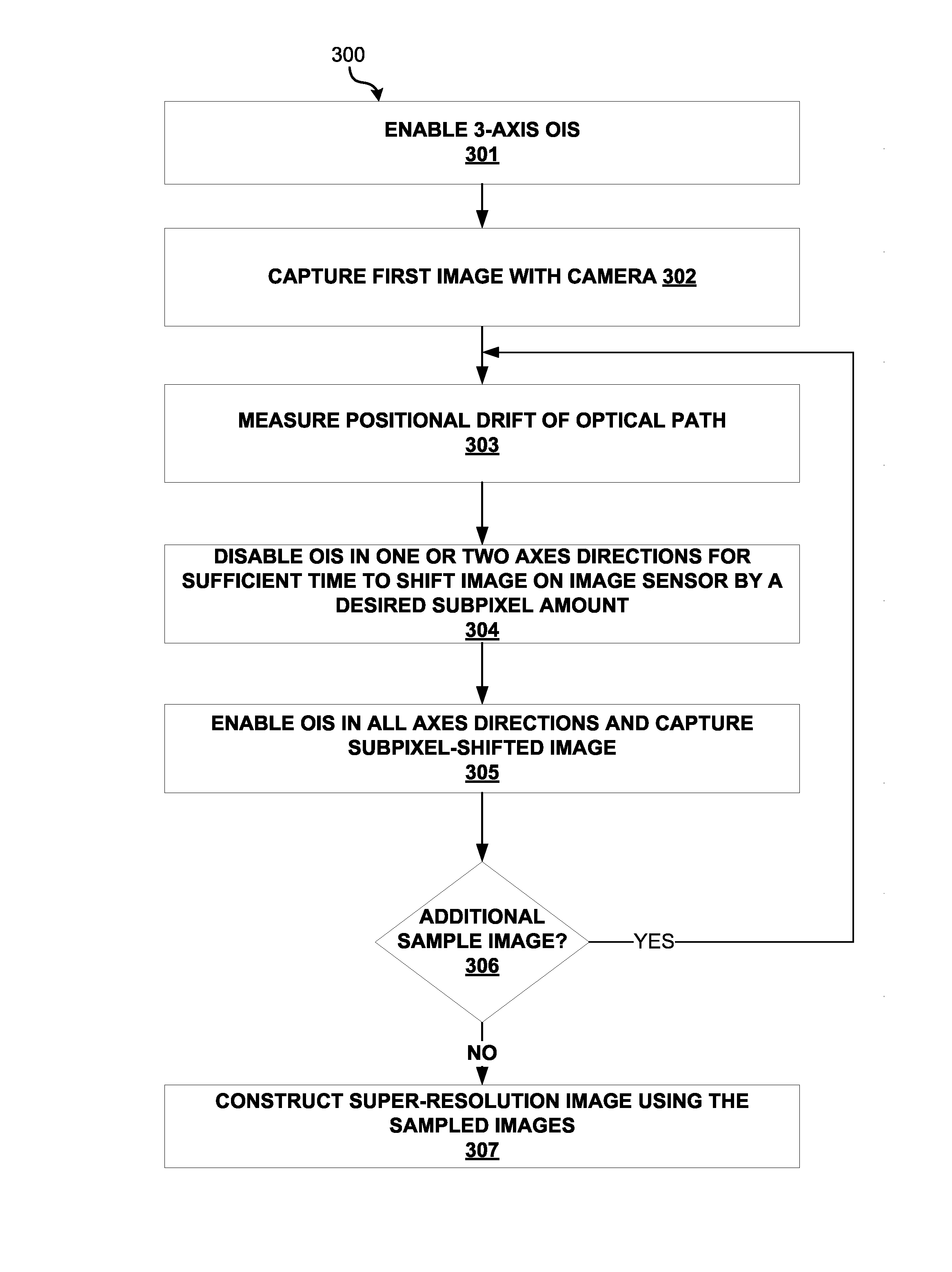
[0030]There are two problems with current implementations of super-resolution imaging techniques in handheld mobile devices that prevent accurate capture of subpixel shifts of a reference picture. First, such implementations rely on 2-axis OIS systems that fail to correct the roll of the imaging device during image capture. However, a 2-axis (pitch and roll) OIS of the image fails to stabilize / compensate for the roll direction of the camera. Thus, the optical path to the image sensor is not completely stabilized and there is motion blur from the variations of the rotation aperture. This motion blur is particularly pronounced along the edges of the image where there is the greatest variability in the rotation aperture. Thus, pitch and yaw (2-axis) OIS-based techniques cannot be used to effectively stabilize an image to less than one pixel in handheld mobile devices.

[0031]Second, current implementations rely on the OIS itself to effectuate specific subpixel movements of the camera len...


PUM


Abstract

Systems and methods are provided for super-resolution imaging using 3-axis OIS. A super-resolution image may be created by enabling optical image stabilization (OIS) in three axes using an OIS system on a camera of an image capturing device; capturing an image of a scene using an image sensor of the camera; shifting the image on the image sensor by a predetermined subpixel amount; capturing the subpixel shifted image; and constructing a super-resolution image of the scene using the image and the subpixel shifted image. In one particular implementation, a position sensor may measure a positional drift of the image sensor after capturing the image. Using this measured positional drift, a time sufficient to shift the image sensor by a predetermined subpixel amount may be determined. The OIS may subsequently be disabled in one or two axes for the determined time.

Description

TECHNICAL FIELD[0001]The present disclosure relates generally to electro-mechanical devices and systems, such as microelectromechanical systems (MEMS). More particularly, various embodiments of the technology disclosed herein are directed to image resolution enhancing techniques that use 3-axis OIS systems.BACKGROUND[0002]Current methods of image zooming include digital zooming and optical zooming. In digital zooming, a picture is cropped to an area of interest and the pixels of that area are blown up. Although the area of interest is “zoomed in” the resolution is significantly less than the physical pixel resolution of the image sensor. An alternative to digital zooming is optical zooming, where a motor moves the optical elements of the camera lens to change the lens' focal length, i.e. the distance between the center of the lens and the image sensor. Although optical zooming samples the actual zoomed image by the physical resolution of the image, its hardware requirements are ill-...

Claims


Application Information

Patent Timeline
IPC IPC(8): H04N5/232G02B26/08
CPCH04N5/23232G02B26/0875H04N5/2257H04N5/23287H04N5/23296H04N5/23258H04N23/682H04N23/90G02B27/646H04N23/54H04N23/57H04N23/951H04N23/6812H04N23/687H04N25/48
Inventor TANG, TONYGUTIERREZ, ROMAN
Owner MEMS DRIVE NANJING CO LTD
Why Eureka
Try Eureka