
In-situ inspection of power generating machinery

a technology for installing power generating machinery and in-situ inspection, which is applied in the direction of color television details, television system details, television systems, etc., can solve the problems of substantial downtime, high cost and time-consuming disassembly and reassembly, and tbc is subject to wear and damag

Inactive Publication Date: 2016-07-21
SIEMENS ENERGY INC
View PDF5 Cites 15 Cited by
  • Summary
  • Abstract
  • Description
  • Claims
  • Application Information

AI Technical Summary

Benefits of technology

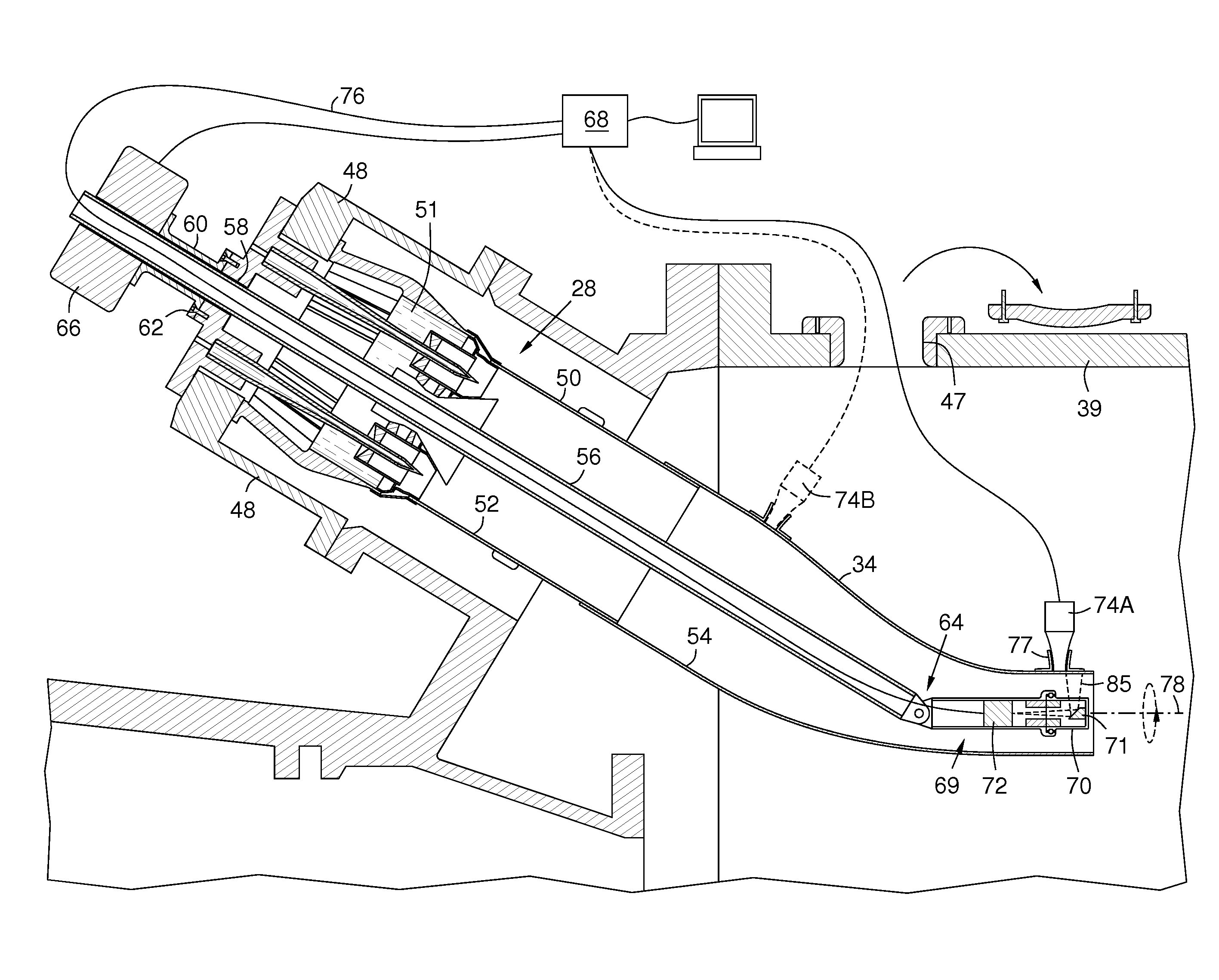
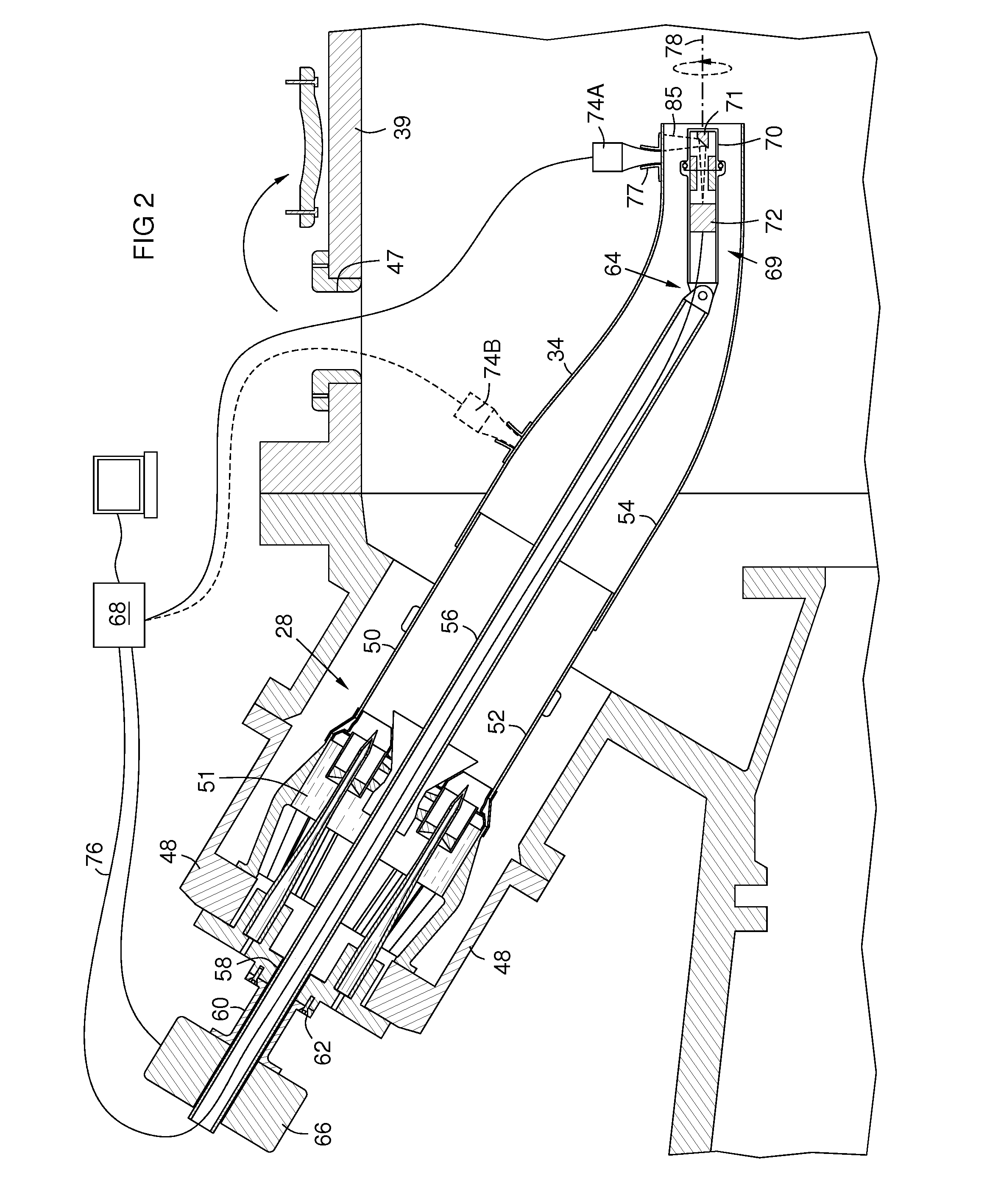
The invention relates to non-destructive inspection of installed power generating machinery, particularly the inner surfaces of gas turbine components. The invention aims to reduce expense and downtime, make more frequent inspection intervals, and extend the safe life of components before replacement or repair. The invention uses thermographic imaging to inspect the inner surfaces of gas turbine components in-situ, which is not possible with traditional disassembly and reassembly methods. The invention provides a camera housing on an inspection scope that can be positioned in the exit end of the transition duct to capture images of the inner surfaces of the combustor and transition duct. The invention allows for more frequent inspection intervals, reduces downtime, and extends the safe life of components before replacement or repair.

Problems solved by technology

The TBC is subject to wear and damage from cyclic thermal expansion, vibrations, heat, and particle impacts.
However, disassembly and reassembly is expensive and time-consuming, causing substantial down-time.
It requires highly trained assembly technicians and relatively heavy equipment.

Method used


Image

  • In-situ inspection of power generating machinery
  • In-situ inspection of power generating machinery
  • In-situ inspection of power generating machinery

Examples


Embodiment Construction

[0008]The inventors recognized that thermographic inspection of the inner surfaces of gas turbine components in-situ would greatly reduce expense and down-time, would make more frequent inspection intervals feasible, and would extend the safe life of the components before replacement or repair. Herein, “in-situ” means the component being inspected remains installed in the engine.

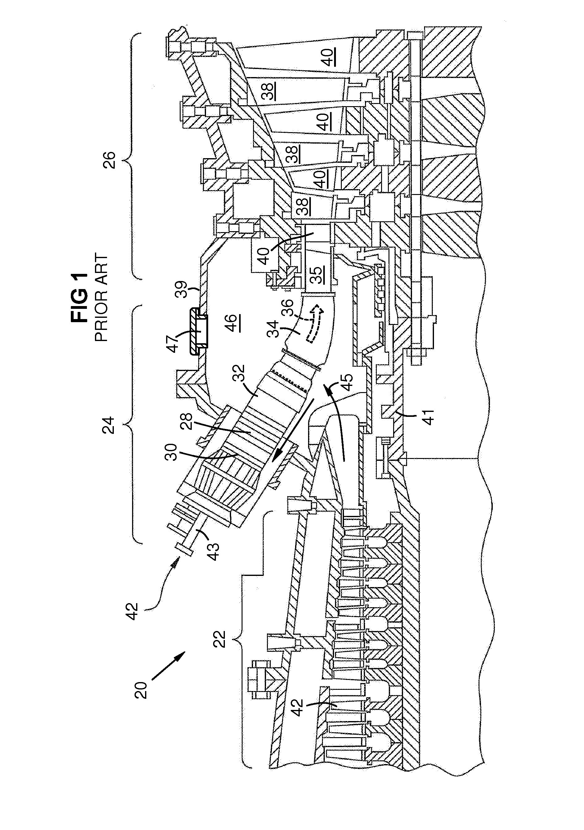
[0009]FIG. 1 is a partial side sectional view of a gas turbine engine 20 with a compressor section 22, a combustion section 24, and a turbine section 26 as known in the art. One combustor 28 of a circular array of combustors is shown. Each combustor 28 has an upstream end 30 and a downstream end 32. A transition duct 34 and an exit piece 35 thereof transfer the combustion gas 36 from the combustor to the first row of airfoils of the turbine section 26, which includes stationary vanes and 38 rotating blades 40. Compressor blades 42 are driven by the turbine section via a common shaft 41. Fuel 42 enters each c...


PUM


Abstract

Thermographic inspection of an internal component (28, 34) of power production equipment (20) by inserting an ultrasound energizer (74A) into an inspection portal of the equipment to contact an exterior of the component, and inserting a camera scope via a second portal into an interior (52, 54) of the component. A motorized drive (66) may mount on a pilot fuel port (58) of a gas turbine to move the scope robotically within a combustor (28) and transition duct (34). A distal camera housing (69) on the scope pivots (64) and contains an infrared camera with a lateral field of view (85) that rotates about an axis 78 by rotating (73) a distal mirror head (70) on the housing or by rotating (73′) the housing (69′). Circumferential sets of thermographic images are acquired by rotating the field of view and translating it along a navigation path in the component interior.

Description

FIELD OF THE INVENTION[0001]This invention relates to non-destructive internal inspection of installed power generating machinery, and more particularly to in-situ thermographic imaging of gas path inner surfaces of gas turbine combustor liners and transition ducts.BACKGROUND OF THE INVENTION[0002]A common industrial gas turbine engine has a circular array of combustors. A transition duct channels combustion gas from each combustor to the first row of turbine blades. Combustion chambers and transition ducts commonly have metal inner liners for the combustion gas path. The inner surfaces of these liners have a thermal barrier coating (TBC), which may include one or more ceramic layers on a bond coat. The TBC is subject to wear and damage from cyclic thermal expansion, vibrations, heat, and particle impacts. The condition of the TBC is critical for protecting the gas path liners and other surrounding parts, so it is regularly inspected. This has been done by partly disassembling the e...

Claims


Application Information

Patent Timeline
Patent Type & Authority Applications(United States)
IPC IPC(8): H04N5/33H04N5/232H04N5/225
CPCH04N5/33H04N5/23238H04N5/2252H04N23/555H04N23/23
Inventor WILLIAMS, JAMES P.DEASCANIS, JOSHUAWILLIAMS, JASON E.LANDY, JAMES F.
Owner SIEMENS ENERGY INC
Learn More