Liquid crystal display device

a liquid crystal display and display device technology, applied in non-linear optics, instruments, optics, etc., to achieve the effect of reducing (efficiently reducing and minimizing) storage voltage variation and increasing the aperture ratio of a pixel

Active Publication Date: 2016-07-28
SAMSUNG DISPLAY CO LTD
View PDF3 Cites 10 Cited by
  • Summary
  • Abstract
  • Description
  • Claims
  • Application Information

AI Technical Summary

Benefits of technology

[0010]Aspects of embodiments of the present invention are directed to a liquid crystal display (LCD) device capable of increasing an aperture ratio of a pixel and efficiently reducing (i.e., minimizing) storage voltage variation.
[0013]However, the voltage dividing transistor may cause the following disadvantages. That is, the voltage dividing transistor may occupy a part of a pixel region, thus decreasing an aperture ratio of the pixel. Further, in a case where the voltage dividing transistor is turned on, a data line and a storage electrode may be electrically connected, such that a storage voltage of the storage electrode may be subject to variation due to a data signal.
[0033]According to embodiments of the present invention, an LCD device may have the following effects.
[0034]First, a level of a data signal applied to a second sub-pixel electrode may be adjusted only with a parasitic capacitor, despite the absence of an additional voltage dividing transistor which is provided in a conventional display device. Accordingly, an aperture ratio of a pixel may increase. Further, since the level of the data signal is adjusted by capacitance of a parasitic capacitor, not by internal resistance of a transistor, the level of the data signal can be more easily controlled.
[0035]Second, since a voltage dividing transistor is not used as described hereinabove, the data line and a storage electrode may not be connected directly. Accordingly, variation in a storage voltage can be efficiently reduced (i.e., minimized).

Problems solved by technology

However, the voltage dividing transistor may cause the following disadvantages.

Method used


Image

  • Liquid crystal display device
  • Liquid crystal display device
  • Liquid crystal display device

Examples


Embodiment Construction

[0047]Advantages and features of the present invention and methods for achieving them will be made clear from embodiments described below in detail with reference to the accompanying drawings. The present invention may, however, be embodied in many different forms and should not be construed as being limited to the embodiments set forth herein. Rather, these embodiments are provided so that this disclosure will be thorough and complete, and will fully convey the scope of the invention to those skilled in the art. The present invention is merely defined by the scope of the claims. Therefore, well-known constituent elements, operations and techniques are not described in detail in the embodiments in order to prevent the present invention from being obscurely interpreted. Like reference numerals refer to like elements throughout the specification.

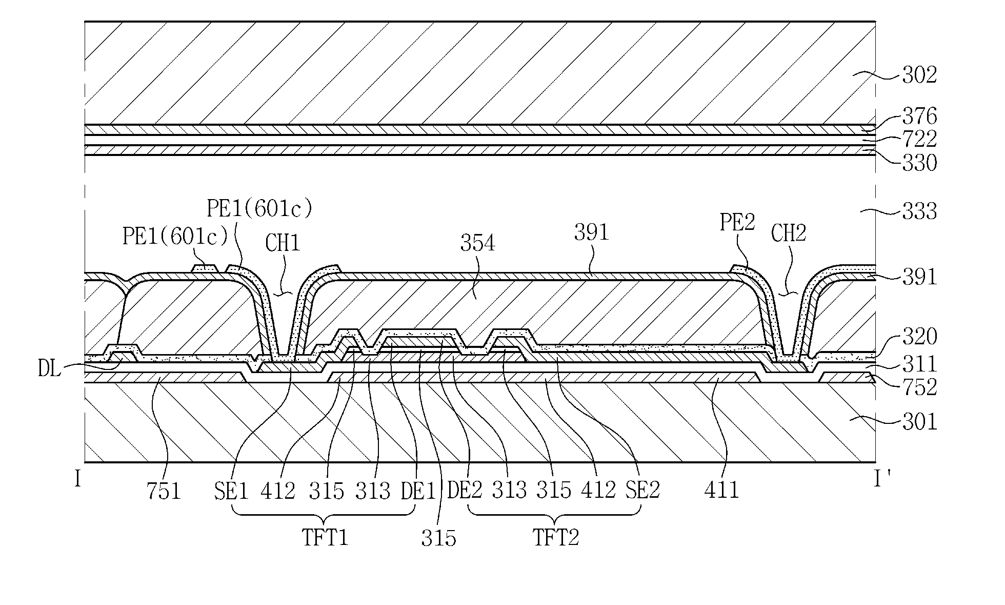
[0048]In the drawings, thicknesses are illustrated in an enlarged manner in order to clearly describe a plurality of layers and areas. Like r...


PUM

PropertyMeasurementUnit
voltageaaaaaaaaaa
voltageaaaaaaaaaa
voltageaaaaaaaaaa

Abstract

A liquid crystal display (LCD) device improves an aperture ratio and stabilizing a storage voltage, including a first substrate; a second substrate opposed to the first substrate; a liquid crystal layer between the first substrate and the second substrate; a gate line and a data line on the first substrate; a semiconductor layer overlapping the gate line; a first drain electrode overlapping the gate line and the semiconductor layer and connected to the data line; a first source electrode overlapping the gate line and the semiconductor layer; a first sub-pixel electrode connected to the first source electrode; a second drain electrode overlapping the gate line and the semiconductor layer and connected to the first drain electrode; a second source electrode overlapping the gate line and the semiconductor layer; and a second sub-pixel electrode connected to the second source electrode. The second source electrode overlaps the gate line more than the first source electrode does.

Description

CLAIM OF PRIORITY[0001]This application claims the priority to and all the benefits accruing under 35 U.S.C. §119 of Korean Patent Application No. 10-2015-0012194, filed on Jan. 26, 2015, with the Korean Intellectual Property Office (KIPO), the disclosure of which is incorporated herein in its entirety by reference.BACKGROUND OF THE INVENTION[0002]1. Field of Disclosure[0003]Embodiments of the present invention relate to a liquid crystal display (LCD) device capable of improving an aperture ratio and stabilizing a storage voltage.[0004]2. Description of the Related Art[0005]An LCD device is a type of flat panel displays (FPDs), which is most widely used these days. The LCD device includes two substrates including electrodes formed thereon and a liquid crystal layer interposed therebetween. Upon applying voltage to two electrodes, liquid crystal molecules of the liquid crystal layer are rearranged, thereby adjusting an amount of transmitted light.[0006]In order to improve visibility,...

Claims


Application Information

Patent Timeline
Patent Type & Authority Applications(United States)
IPC IPC(8): G02F1/1343
CPCG02F2001/134345G02F1/134309G02F1/133707G02F1/1368G02F2201/40G02F1/134345G02F1/136286
Inventor YANG, GUNWOOKIM, KEUNWOOKIM, YOUNGSEUNGPARK, SOOYOUNGJEON, KICHANPARK, MUNSOO
Owner SAMSUNG DISPLAY CO LTD
Why Eureka
Try Eureka