Chain link for a link chain and tool magazine with link chain

a technology of chain link and tool magazine, which is applied in the direction of manufacturing tools, metal-working machine components, positioning apparatuses, etc., can solve the problem of limited tool exchange speed, and achieve the effect of high magazine capacity and high stability

Active Publication Date: 2016-08-04
DECKEL MAHO SEEBACH GMBH
View PDF9 Cites 3 Cited by
  • Summary
  • Abstract
  • Description
  • Claims
  • Application Information

AI Technical Summary

Benefits of technology

The objective of this invention is to create a tool magazine for a machine tool that can hold many tools while being small and stable enough to handle changes in motion during use.

Problems solved by technology

The technical problem addressed in this patent relates to improving the efficiency and performance of machine tools equipped with a tool magazine. Specifically, there is a limit to the amount of tools that can be accommodated within the tool magazine without compromising its stability or the speed of tool replacement.

Method used


Image

  • Chain link for a link chain and tool magazine with link chain
  • Chain link for a link chain and tool magazine with link chain
  • Chain link for a link chain and tool magazine with link chain

Examples


Embodiment Construction

[0058]In the following, the present invention is specified and explained by means of exemplary embodiments and the exemplary figures.

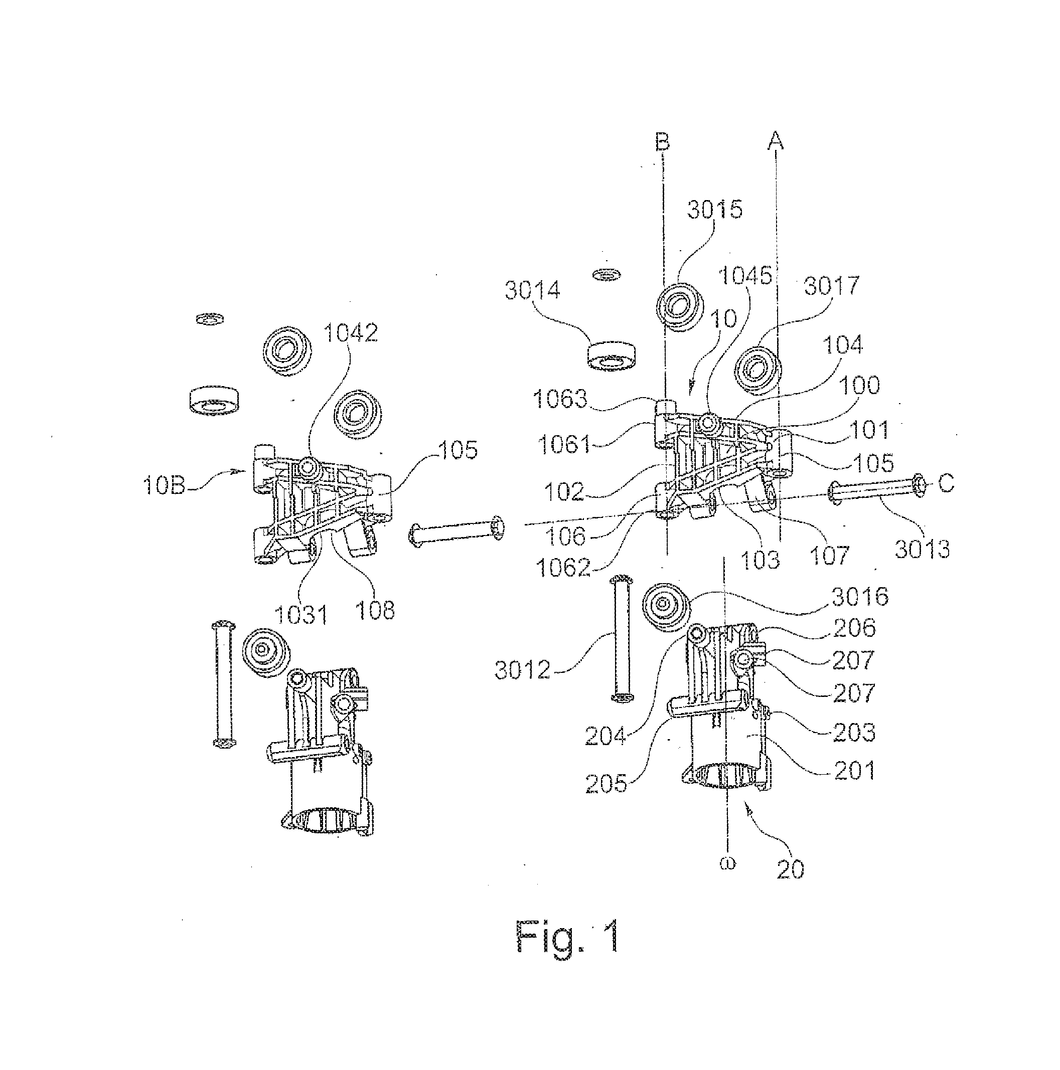
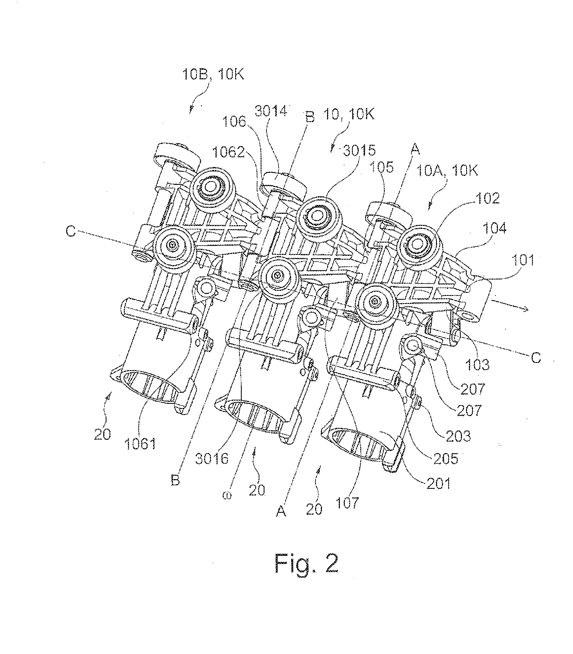
[0059]FIG. 1 shows an exemplary embodiment of a chain link 10 according to the invention and the relative arrangement thereof with respect to an adjacent chain link 10B as well as two tool receptacles 20 without tool. Also shown are the connection element 3012 which is made as a pin and serves tor connecting the chain links 10 and 10B, the connection element 3013 which is made as a pin and serves for connecting the chain link 10 to a receptacle 20 and the rolling bearings 3014-3016 for supporting the chain links 10, 10B and the receptacles 20.

[0060]The chain link 10 has a planar shape, wherein the base area 100 thereof has the shape of a trapezoid or a triangle with cut-off tip. The base area 100 is confined by four sides 101-104, wherein the first side 101 is the shortest side of the trapezoid and is parallel to the second side 102. The first and seco...


PUM


Abstract

A chain link includes a base area, confined by four sides, and first to third link portions respectively on first to third sides. The first and second link portions respectively receive first and second connection elements for connecting the chain link to first and second adjacent chain links, and respectively and relatively define first and second rotational axes of adjacent first and second chain links. The third link portion receives a third connection element for connecting the chain link to a tool receptacle and defines a third rotational axis of a rotary motion of the tool receptacle in relation to the chain link. The first and second axes define a first plane, the first plane is parallel to the chain link base area, and the third axis lies outside the first plane. A tool magazine for a machine tool includes a link chain from chain links for the tool transport.

Description


Claims


Application Information

Patent Timeline
Owner DECKEL MAHO SEEBACH GMBH
Why Eureka
Try Eureka