
Electronically controlled internal damper

a technology of electromagnetic control and damper, which is applied in the direction of shock absorbers, mechanical equipment, transportation and packaging, etc., can solve the problems of difficult to reduce the damping force of soft mode during rebound stroke, adverse effect in medium-speed or high-speed sections, etc., and achieve the effect of reducing the damping force and improving ride comfor

Active Publication Date: 2016-08-04
HL MANDO CORP
View PDF3 Cites 4 Cited by
  • Summary
  • Abstract
  • Description
  • Claims
  • Application Information

AI Technical Summary

Benefits of technology

The patent is about a device that reduces the roughness of a car's ride by controlling the movement of the car's suspension. This device helps to improve the comfort of the ride by reducing the low-speed damping force of a soft mode in the suspension. It is designed to be installed in vehicles and can be controlled electronically to adjust the suspension's movement. This invention aims to improve the overall quality of the driving experience.

Problems solved by technology

In such electronically controlled internal dampers, since a passage area of a cylinder increases, it is difficult to reduce a low-speed damping force of a soft mode during a rebound stroke.
However, such a design modification causes an increase in a whole valve size or a reduction in a disk size, thus producing adverse effect in a medium-speed or high-speed section.

Method used


Image

  • Electronically controlled internal damper
  • Electronically controlled internal damper
  • Electronically controlled internal damper

Examples


Embodiment Construction

[0021]The advantages and features of the present invention and methods for achieving them will become more apparent from the following embodiments that are described in detail in conjunction with the accompanying drawings.

[0022]However, the present invention is not limited to the following embodiments, but may be embodied in various forms.

[0023]These embodiments are provided so that this disclosure will be thorough and complete, and will fully convey the scope of the invention to those skilled in the art.

[0024]The scope of the present invention is defined by the appended claims.

[0025]Therefore, in some embodiments, detailed descriptions of well-known elements, operations, and technologies will be omitted for simplicity and clarity.

[0026]Throughout the disclosure, like reference numerals refer to like elements. The terminology used herein is intended to just describe particular embodiments and is not intended to limit the present invention.

[0027]In this specification, the singular fo...


PUM


Abstract

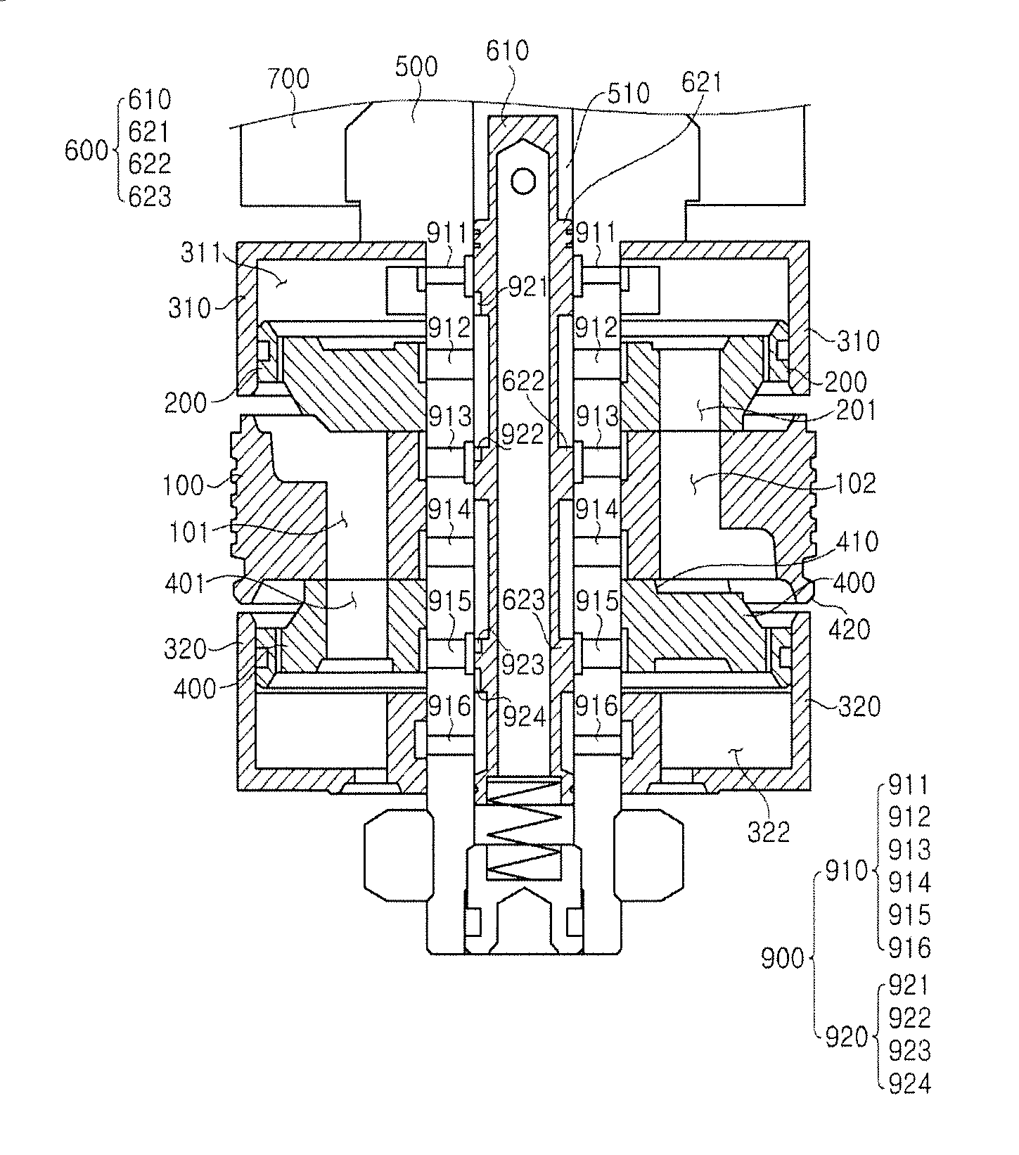
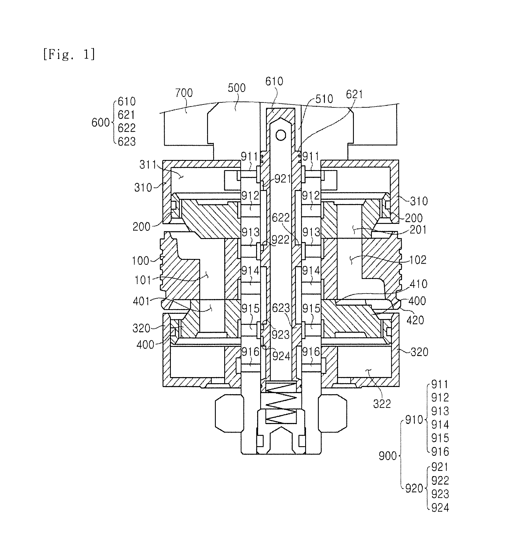
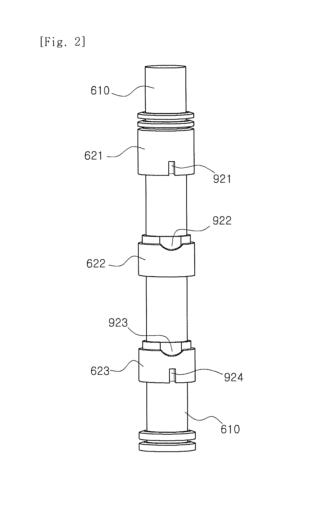
An electronically controlled internal damper is provided. Due to a structure in which a valve unit is mounted on a spool rod along which a driven spool reciprocates and a damping unit is provided in an outer peripheral surface of the driven spool and the spool rod, it is possible to improve ride comfort by reducing a low-speed damping force of a soft mode in the driven spool and the spool rod without increasing their sizes.

Description

CROSS-REFERENCE(S) TO RELATED APPLICATION[0001]This application claims priority of Korean Patent Application No. 10-2015-0016155, filed on Feb. 2, 2015, in the Korean Intellectual Property Office, which is hereby incorporated by reference in its entirety.BACKGROUND OF THE INVENTION[0002]1. Field of the Invention[0003]The present invention relates to an electronically controlled internal damper, and more particularly, to an electronically controlled internal damper that is capable of improving ride comfort by reducing a low-speed damping force of a soft mode without increasing the sizes of a driven spool and a spool rod.[0004]2. Description of the Related Art[0005]In most of the conventional electronically controlled internal dampers, a bypass passage is disposed only on a rebound side.[0006]In such electronically controlled internal dampers, since a passage area of a cylinder increases, it is difficult to reduce a low-speed damping force of a soft mode during a rebound stroke.[0007]...

Claims


Application Information

Patent Timeline
Patent Type & Authority Applications(United States)
IPC IPC(8): B60G17/08B60G13/08F16F9/48
CPCF16F9/48F16F9/34F16F9/466F16F9/3405
Inventor KIM, EUN JOONG
Owner HL MANDO CORP
Learn More