
Boundary layer control assembly for an aircraft airfoil and method of controlling a boundary layer

Inactive Publication Date: 2016-08-04
HAMILTON SUNDSTRAND CORP
View PDF2 Cites 1 Cited by
  • Summary
  • Abstract
  • Description
  • Claims
  • Application Information

AI Technical Summary

Benefits of technology

The patent describes a way to control the flow of air over a propeller blade by using a heating element to disrupt the smooth flow of air and a cooling system to delay the formation of turbulent flow. This technology can reduce the energy needed to move air and improve the efficiency of propellers.

Problems solved by technology

All efforts are traditionally heavy, large, costly, and difficult for maintenance purposes.
This technique, along with other prior efforts require added weight, high installation cost, and routine maintenance, which are all undesirable from a manufacturer's and operator's standpoint.
Efforts to implement the aforementioned laminar flow control assemblies into rotating wings, such as propeller blades or rotor blades, are subject to additional and more severe difficulties due to the rotatable nature of the airfoils.

Method used


Image

  • Boundary layer control assembly for an aircraft airfoil and method of controlling a boundary layer
  • Boundary layer control assembly for an aircraft airfoil and method of controlling a boundary layer

Examples


Embodiment Construction

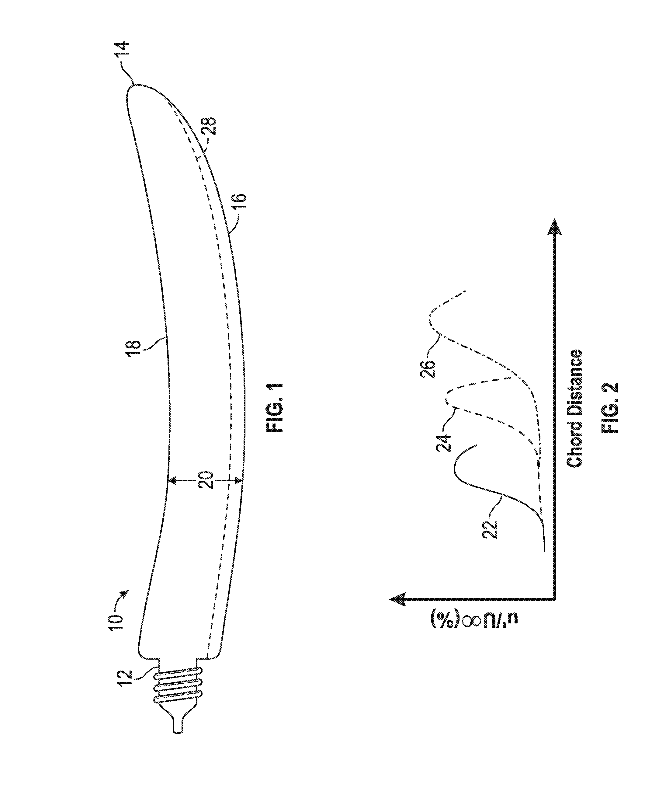
[0008]Referring to FIG. 1, a rotating airfoil is generally illustrated and relates to any airfoil used to facilitate flight for a vehicle. In the illustrated embodiment, the aircraft airfoil is depicted as a propeller blade 10. However, it is to be appreciated that the embodiments described herein may be beneficial for a rotary wing vehicle such as a helicopter or a fixed wing vehicle such as a traditional airplane, as well.

[0009]The propeller blade 10 extends from a root portion 12 to a tip portion 14 to define a span length of the propeller blade 10. In a substantially transverse direction, the propeller blade 10 extends from a leading edge 16 to a trailing edge 18 to define a chord length 20. The particular dimensions of the propeller blade will vary depending upon the particular application of use.

[0010]During operation of the propeller blade 10, a fluid (e.g., air) passes over the propeller blade 10 in a direction going from the leading edge 16 to the trailing edge 18 and forms...


PUM


Abstract

A boundary layer control assembly for an aircraft airfoil includes a leading edge and a trailing edge spaced from the leading edge to form a chord length. The boundary layer control assembly also includes a heating element disposed proximate the leading edge to heat a boundary layer formed along the surface of the aircraft airfoil.

Description

BACKGROUND OF THE INVENTION[0001]The embodiments herein relate to aircraft, helicopter rotor, and aircraft propeller airfoils and, more particularly, to a boundary layer control assembly for such airfoils, as well as a method of controlling a boundary layer.[0002]It is desirable to control the boundary layer along aircraft airfoil surfaces for a number of reasons. For example, by maintaining a laminar flow along the airfoil surface benefits associated with reduced aerodynamic drag and, in the case of propeller or propulsion systems, higher propulsive efficiency are achieved. These efforts may be referred to as laminar flow control techniques. All efforts are traditionally heavy, large, costly, and difficult for maintenance purposes. One such technique involves boundary layer suction, for example, which requires pumps among other components. This technique, along with other prior efforts require added weight, high installation cost, and routine maintenance, which are all undesirable ...

Claims


Application Information

Patent Timeline
IPC IPC(8): B64C21/00B64C23/00B64D15/12
CPCB64C21/00B64C23/005B64C2230/10B64C2230/28B64D15/12Y02T50/10Y02T50/60
Inventor LIN, RAY-SINGTILLMAN, THOMAS G.HENZE, CHAD M.
Owner HAMILTON SUNDSTRAND CORP
Learn More