Stirling cryocooler

a cryocooler and stirling technology, applied in the field of stirling cryocoolers, can solve the problem of reducing the refrigerating capacity of stirling cryocoolers

Inactive Publication Date: 2016-08-04
SUMITOMO HEAVY IND LTD
View PDF2 Cites 3 Cited by
  • Summary
  • Abstract
  • Description
  • Claims
  • Application Information

AI Technical Summary

Problems solved by technology

Heat having intruded this way decreases the refrigerating capacity of the Stirling cryocooler.

Method used


Image

  • Stirling cryocooler
  • Stirling cryocooler
  • Stirling cryocooler

Examples


Embodiment Construction

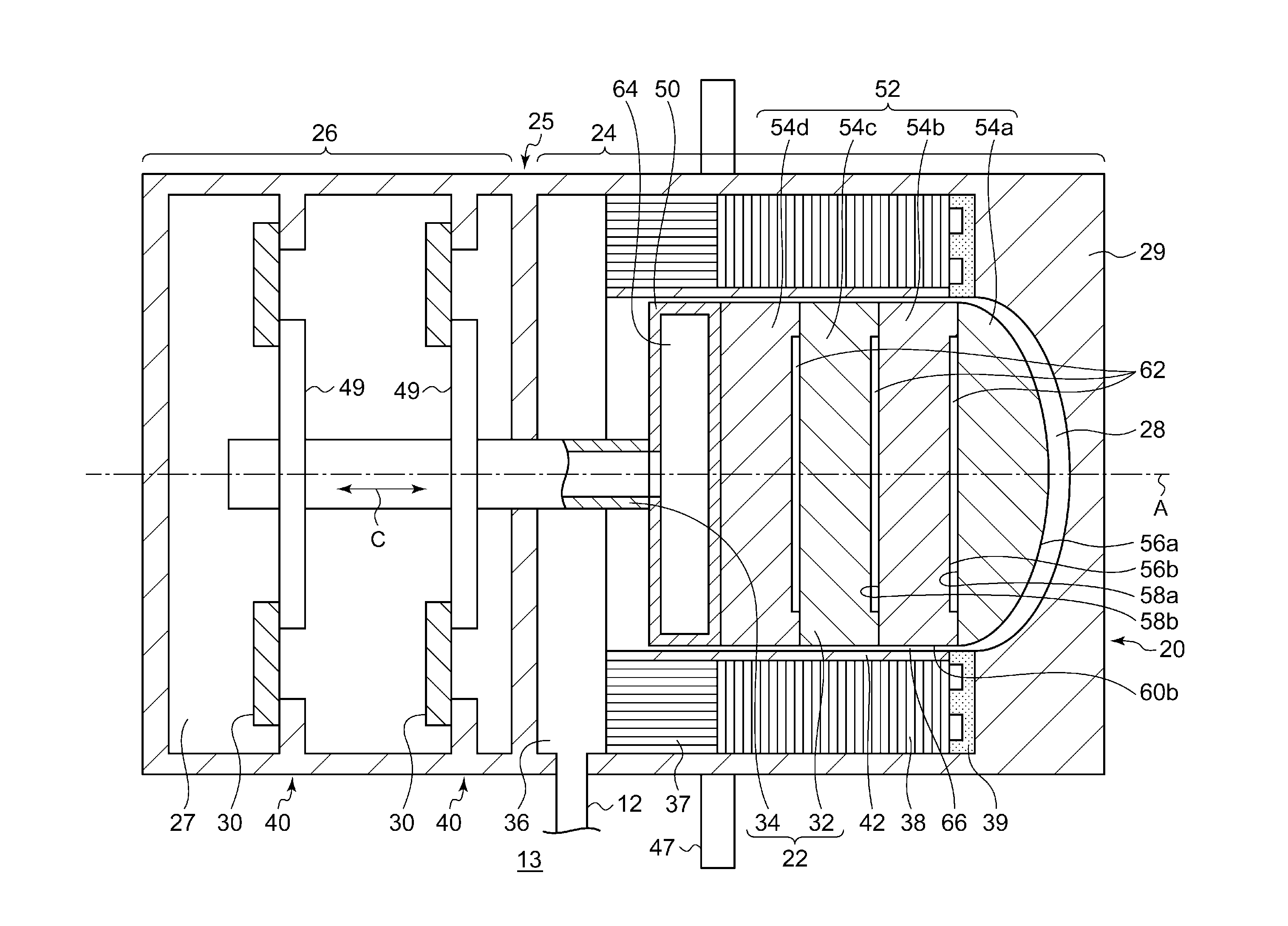
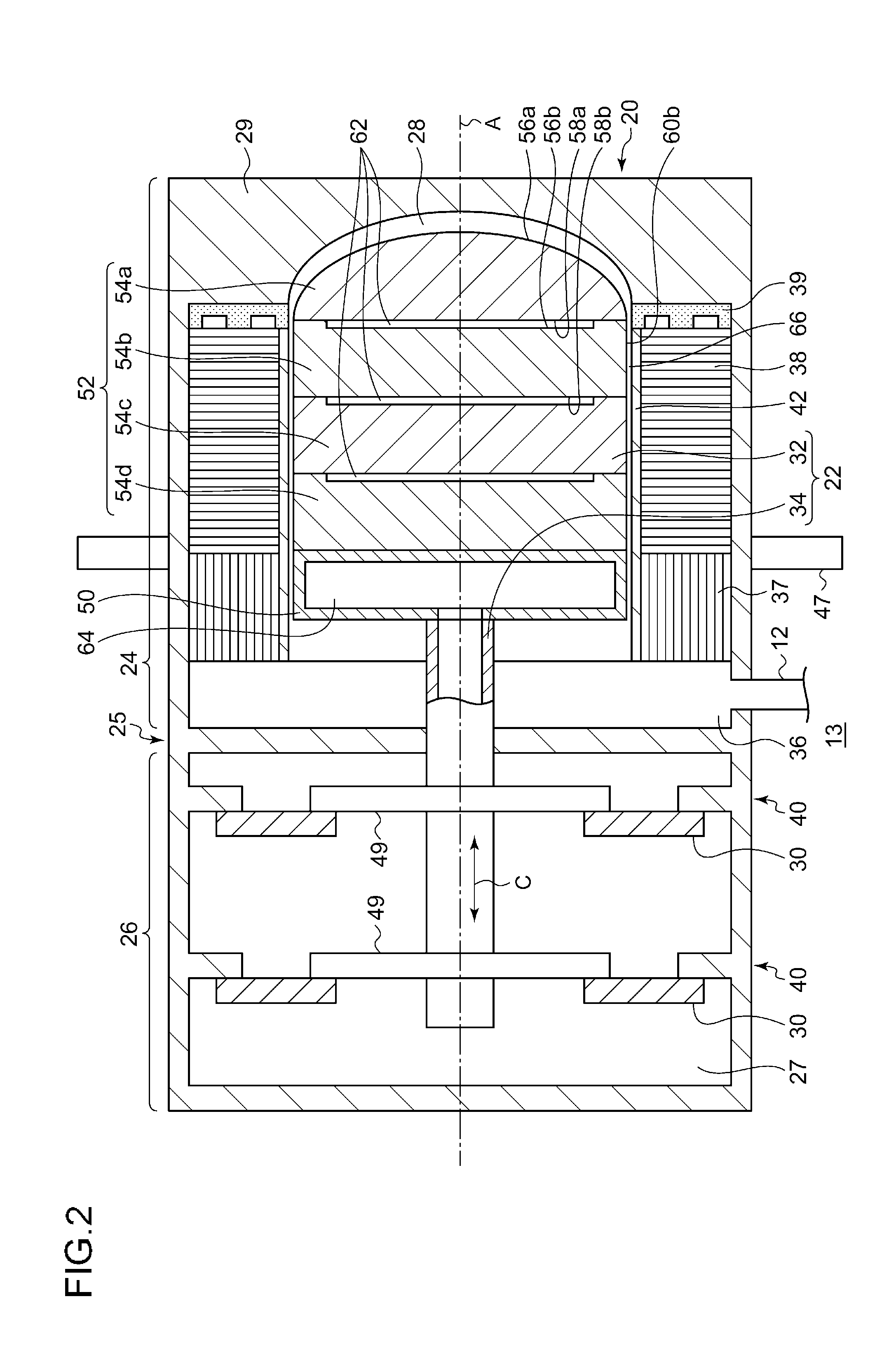
[0011]It is desirable to decrease heat transmitted through a displacer in an expander of a Stirling cryocooler.

[0012]In addition, certain embodiments of the invention include arbitrary combinations of the above-described components, or components or expressions of the present invention that may be interchangeable with each other between methods, devices, systems, or the like.

[0013]According to certain embodiments of the invention, it is possible to decrease heat transmitted through the displacer in the expander of the Stirling cryocooler.

[0014]Hereinafter, certain embodiments of the invention will be described in detail with reference to the drawings. In addition, in descriptions thereof, the same reference numerals are assigned to the same elements, and overlapping descriptions are appropriately omitted. In addition, configurations described below are exemplified, and do not limit a scope of the present invention.

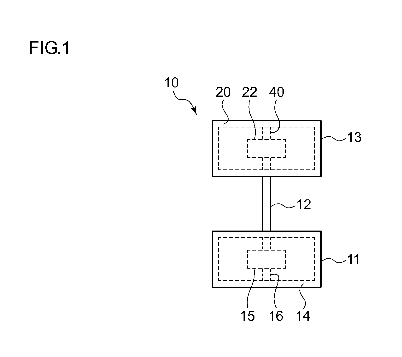
[0015]FIG. 1 is a view schematically showing a Stirling cryocooler 10...


PUM


Abstract

A Stirling cryocooler includes a displacer having a displacer base portion disposed on a center axis and a displacer tip portion aligned along the center axis, extending from the displacer base portion to a working-gas expansion space, and a regenerator disposed surrounding the displacer tip portion such as to guide reciprocating travel of the displacer along the center axis. The displacer tip portion includes a plurality of platelike components arranged along the center axis, with each of the plurality of platelike components being furnished with a component side surface defining a portion of the outer surface of the displacer tip portion. The plurality of platelike components form working gas layers between pairs of adjoining components, and/or are formed of a synthetic resin material.

Description

RELATED APPLICATIONS[0001]Priority is claimed to Japanese Patent Application No. 2015-015718, filed Jan. 29, 2015, the entire content of which is incorporated herein by reference.BACKGROUND[0002]1. Technical Field[0003]Certain embodiments of the invention relate to a Stirling cryocooler, and particularly, to an expander of a Stirling cryocooler.[0004]2. Description of Related Art[0005]A displacer is provided in an expander of a Stirling cryocooler. One end of the displacer is disposed on a “low temperature” portion of the expander, and the other end is disposed on a “normal temperature” portion thereof. Accordingly, a temperature gradient is produced in the displacer when the cryocooler is used. Consequently, via the displacer heat from the normal temperature portion invades the low temperature portion. Heat having intruded this way decreases the refrigerating capacity of the Stirling cryocooler.SUMMARY[0006]According to an aspect of the present invention, there is provided a Stirli...

Claims


Application Information

Patent Timeline
Patent Type & Authority Applications(United States)
IPC IPC(8): F25B9/14
CPCF25B9/14
Inventor NAKANO, KYOSUKEHIRATSUKA, YOSHIKATSUYUMOTO, KENTA
Owner SUMITOMO HEAVY IND LTD
Why Eureka
Try Eureka