Air conditioner

Active Publication Date: 2016-08-04
FUJITSU GENERAL LTD
View PDF14 Cites 23 Cited by
  • Summary
  • Abstract
  • Description
  • Claims
  • Application Information

AI Technical Summary

Benefits of technology

[0015]According to the air conditioner of the present invention that is configured as described as above, the compressor is driven at the activation rotational speed in accordance with the total sum of the capacity of the flow rate adjustment valve or at the activation rotational speed in accordance with the total sum of the capacity of the flow rate adjustment valve and the refrigerant pipe length for the predetermined time from the start of the defrosting operation. Accordingly, even in the case where a refrigerant circulation amount at the start of the defrosting operation is reduced by the small total sum of the capacity

Problems solved by technology

When the outdoor heat exchanger is frosted, ventilation to the outdoor heat exchanger is inhibit

Method used


Image

  • Air conditioner
  • Air conditioner
  • Air conditioner

Examples


example 1

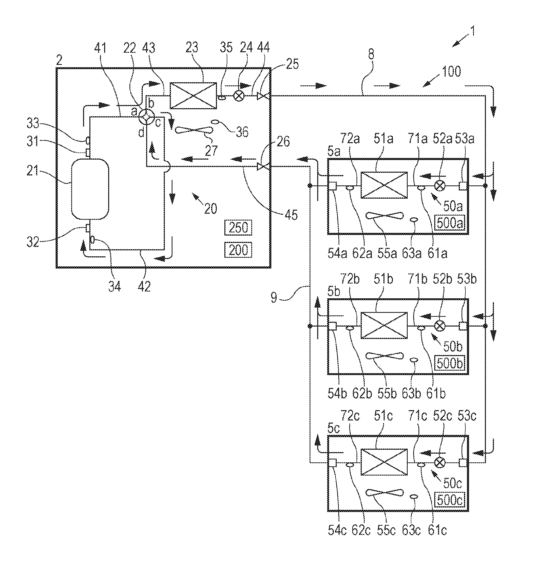
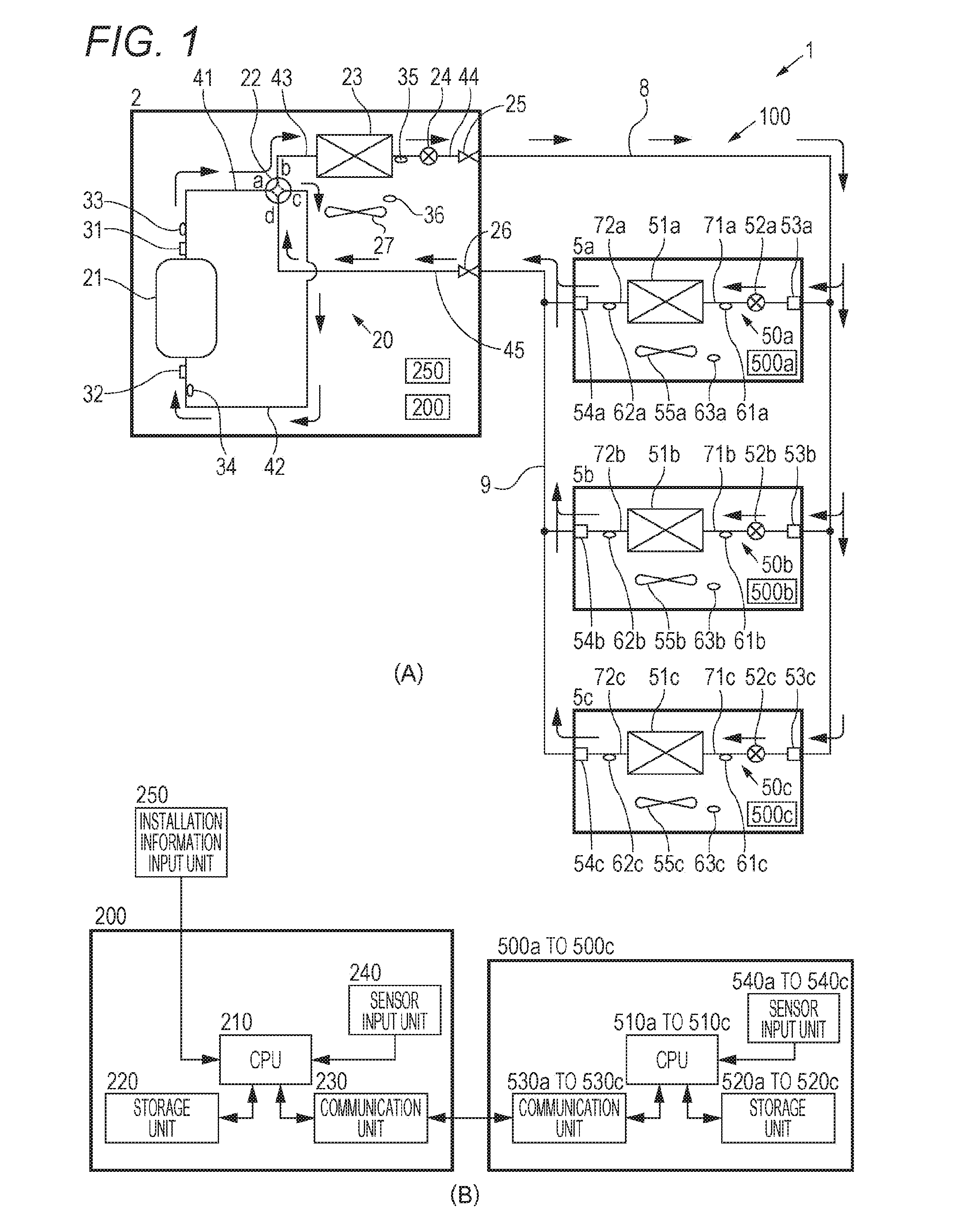
[0021]As depicted in FIG. 1(A), an air conditioner 1 of this example includes: one outdoor unit 2 that is installed outdoors; and three indoor units 5a to 5c that are coupled in parallel to the outdoor unit 2 via a liquid pipe 8 and a gas pipe 9. In detail, one end of the liquid pipe 8 is coupled to a closing valve 25 of the outdoor unit 2, and the other end thereof is branched and respectively coupled to liquid pipe coupling portions 53a to 53c of the indoor units 5a to 5c. In addition, one end of the gas pipe 9 is coupled to a closing valve 26 of the outdoor unit 2, and the other end thereof is branched and respectively coupled to gas pipe coupling portions 54a to 54c of the indoor units 5a to 5c. Thus, a refrigerant circuit 100 of the air conditioner 1 is configured.

[0022]First, the outdoor unit 2 will be described. The outdoor unit 2 includes a compressor 21, a four-way valve 22 as a flow passage switching unit, an outdoor heat exchanger 23, an outdoor expansion valve 24, the cl...

example 2

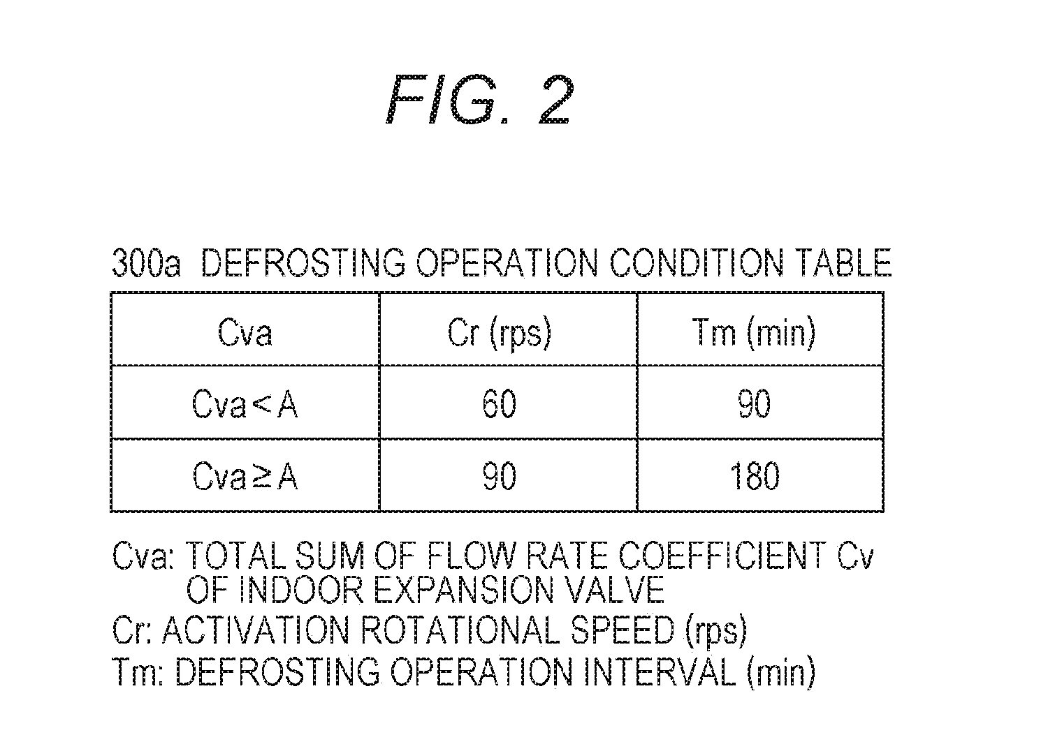
[0085]Next, a description will be made on a second embodiment of the air conditioner of the present invention by using FIG. 4. It should be noted that, since the configuration and the operation performance of the air conditioner and changing of the activation rotational speed of the compressor and the defrosting operation interval in the defrosting operation in accordance with the total sum of the flow rate coefficients Cva are the same as those in the first embodiment, the detailed description thereon will not be made in this embodiment. What differs from the first embodiment is that the activation rotational speed of the compressor and the defrosting operation interval are defined in consideration of a length of the refrigerant pipe for coupling the outdoor unit and the indoor units in addition to the total sum of the flow rate coefficients Cva in a defrosting operation condition table.

[0086]Similar to the defrosting operation condition table 300a depicted in FIG. 2, a defrosting ...


PUM


Abstract

An outdoor unit control unit 200 has a defrosting operation condition table 300a that defines an activation rotational speed Cr in accordance with a total sum of flow rate coefficients Cva that is a total sum of flow rate coefficients Cv representing capacities of indoor expansion valves 52a to 52c. The outdoor unit control unit 200 calculates the total sum of the flow rate coefficients Cva by adding the flow rate coefficient Cv of each of the indoor expansion valves 52a to 52c, and refers to the defrosting operation condition table 300a, so as to determine the activation rotational speed Cr. Then, the outdoor unit control unit 200 activates a compressor 21 at the determined activation rotational speed Cr when starting a defrosting operation, maintains this activation rotational speed Cr for a predetermined time from the start of the defrosting operation, and drives the compressor 21.

Description

TECHNICAL FIELD[0001]The present invention relates to an air conditioner in which at least one outdoor unit and at least one indoor unit are mutually coupled by plural refrigerant pipes.BACKGROUND ART[0002]An air conditioner in which at least one outdoor unit and at least one indoor unit are mutually coupled by plural refrigerant pipes has been suggested. In the case where a temperature of an outdoor heat exchanger becomes equal to or less than 0° C. when this air conditioner performs a heating operation, the outdoor heat exchanger may be frosted. When the outdoor heat exchanger is frosted, ventilation to the outdoor heat exchanger is inhibited by the frost, and thus heat exchange efficiency in the outdoor heat exchanger may be degraded. Thus, when frosting occurs to the outdoor heat exchanger, a defrosting operation has to be performed to defrost the outdoor heat exchanger.[0003]For example, in an air conditioner described in Patent Literature 1, an outdoor unit that includes a com...

Claims


Application Information

Patent Timeline
IPC IPC(8): F25B47/02
CPCF24F3/065F24F11/0076F25B47/025F24F2011/0089F24F2011/0063F24F2011/0083F24F11/42F24F11/64F24F11/70F24F11/85F25B49/02F25B2313/006F25B2313/0233F25B2313/0293F25B2313/0294F25B2313/0314F25B2313/0315F25B2600/025F25B2700/00F25B2700/1931F25B2700/1933F25B2700/21151F25B2700/21152
Inventor KIMURA, TAKASHIHAYASHI, KUNIKO
Owner FUJITSU GENERAL LTD
Why Eureka
Try Eureka