Advanced optics for irst sensor

Active Publication Date: 2016-08-04
RAYTHEON CO
View PDF1 Cites 11 Cited by
  • Summary
  • Abstract
  • Description
  • Claims
  • Application Information

AI Technical Summary

Benefits of technology

[0003]Aspects and embodiments relate to optical sensor systems in general and in particular to a multi-function airborne sensor system that includes an IRST function and has an extended elevation field of view. In particular, and as discussed in more detail below, aspects and embodiments are directed to an airborne sensor system in which the optics are configured around a

Problems solved by technology

Some attempts to further increase the elevation field of view, and therefore the elevation aperture*FOV product, have involved the use of refractive optics; however, the

Method used


Image

  • Advanced optics for irst sensor
  • Advanced optics for irst sensor
  • Advanced optics for irst sensor

Examples


Embodiment Construction

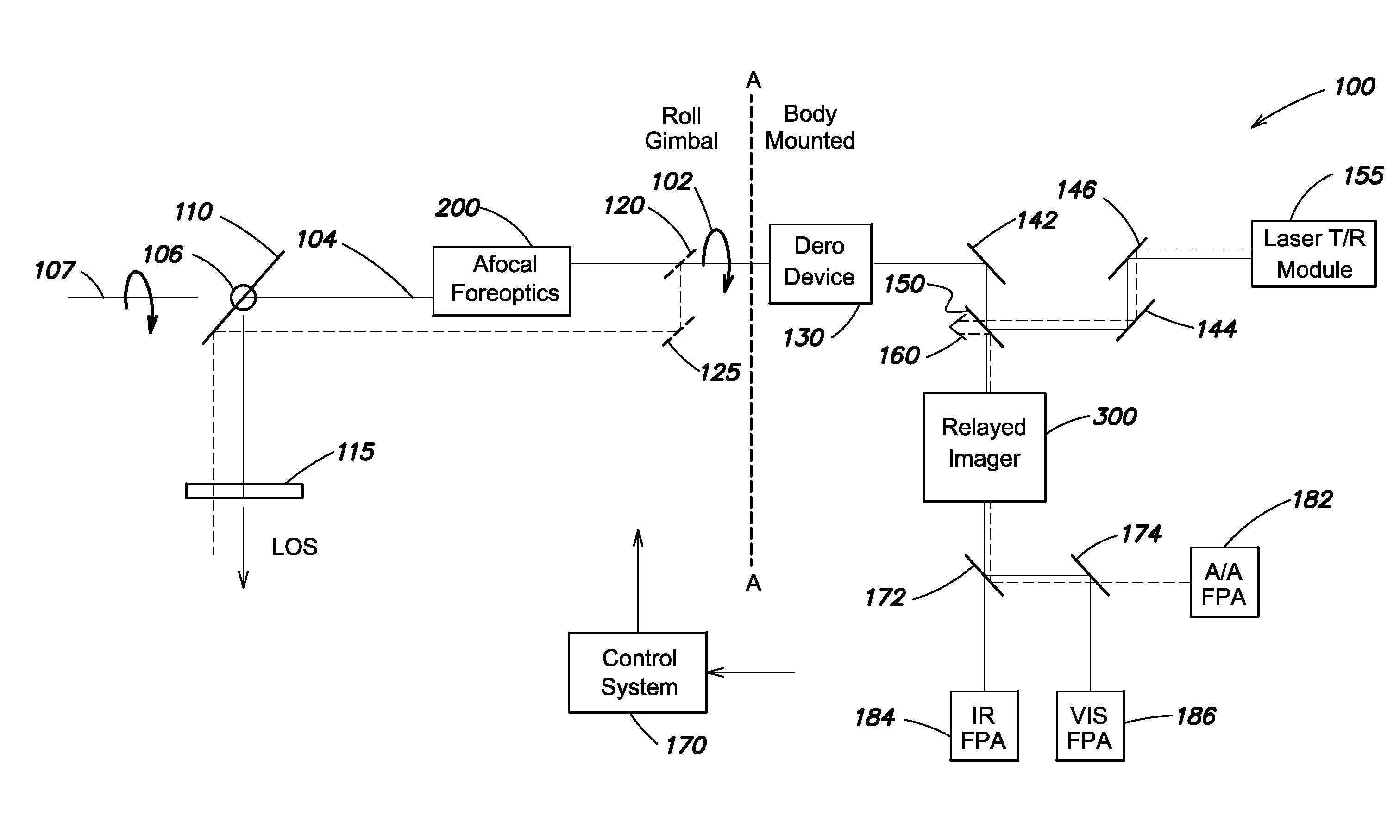
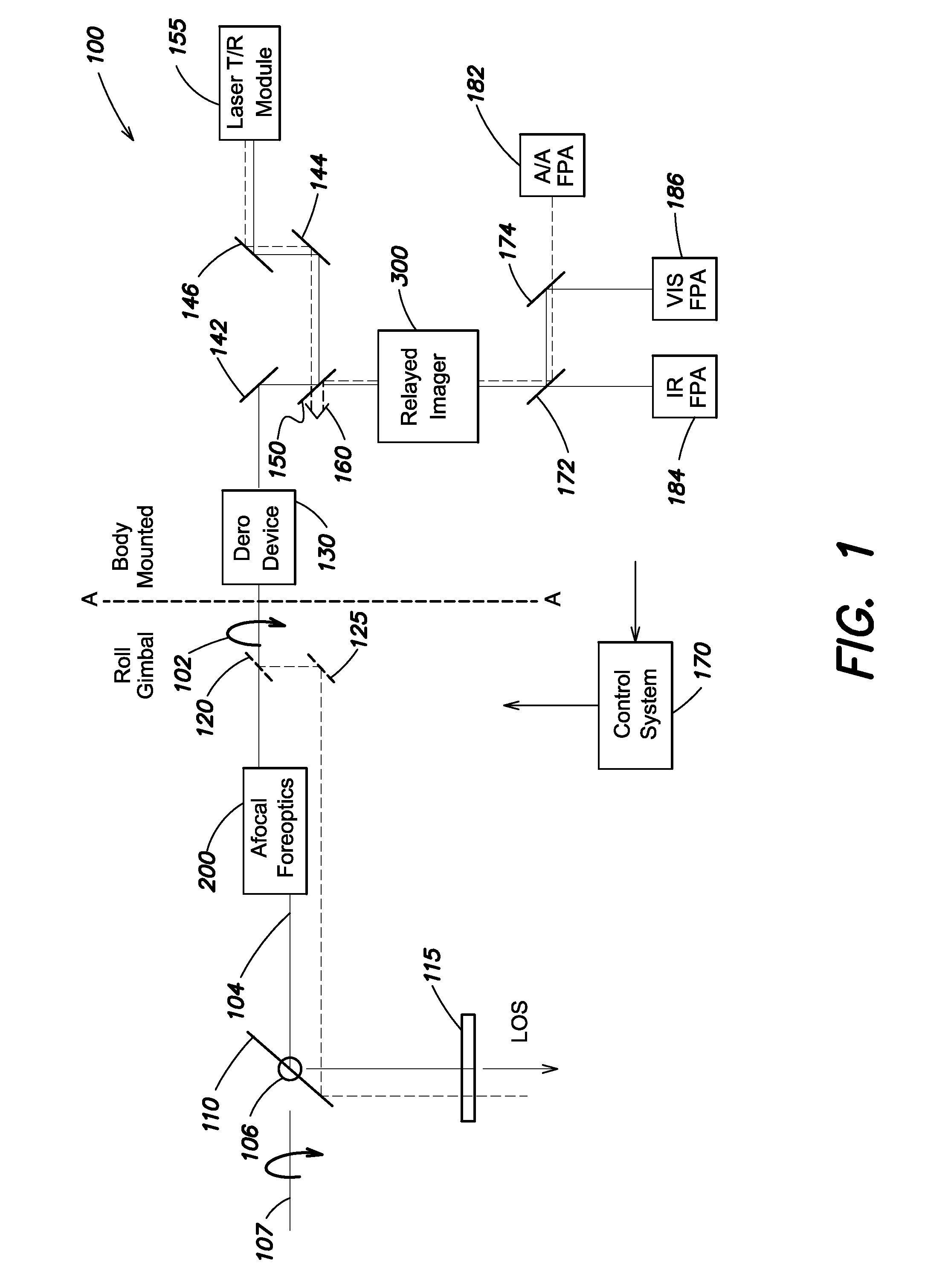
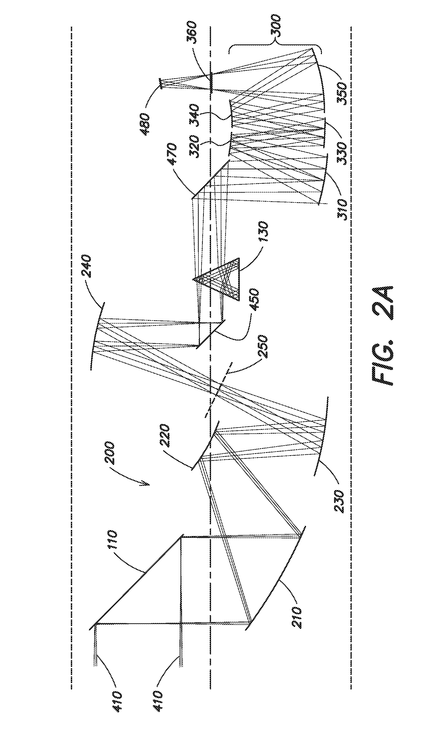
[0025]Aspects and embodiments are directed to an optical configuration for a multi-function gimbaled airborne sensor system that provides significantly increased field of view (FOV) in elevation, while maintaining all the advantages and capabilities of an all-reflective optical system. As discussed above, conventional IRST (infrared search and track) capable airborne sensor systems have limited FOV in elevation. For example, sensor systems using on-gimbal foreoptics having a folded all-reflective three-mirror anastigmat optical form, such as that disclosed in U.S. Pat. No. 8,759,735, for example, are limited by size, image quality, and distortion constraints to approximately 2.5° FOV in elevation (EL FOV). Although certain approaches using refractive optics have achieved ˜3.0° EL FOV, such designs are severely limited in spectral coverage, have low transmission, and suffer from high thermal sensitivity due to the refractive nature of the optics. There is a need for IRST-capable sens...


PUM


Abstract

An optical sensor system having an extended elevation field of view and in which the optics are configured around an all-reflective four-mirror reimaging anastigmat used for afocal foreoptics and an all-reflective five-mirror reimaging anastigmat used for imaging optics. One example of an optical sensor system includes afocal foreoptics configured to receive and collimate electromagnetic radiation, the afocal foreoptics including an all-reflective, reimaging four-mirror anastigmat, an imaging detector, focal imaging optics positioned between the afocal foreoptics and the imaging detector and configured to receive the collimated beam of electromagnetic radiation from the afocal foreoptics and to focus the beam of electromagnetic radiation onto the imaging detector, the focal imaging optics including a reimaging five-mirror anastigmat, wherein a field of view of the system is determined at least in part by a combination of the afocal foreoptics and the focal imaging optics and covers at least 5 degrees in elevation.

Description

BACKGROUND[0001]There are numerous applications for imaging sensors that provide infrared search and track (IRST), targeting or standoff reconnaissance functions, such as on an aircraft including an unmanned aerial vehicle (UAV) platform for standoff reconnaissance or on a jet aircraft for IRST, targeting (i.e., target location and designation) and standoff reconnaissance (e.g., survey or observation to collect image information). Additionally, some IRST systems include laser range-finding, and / or coherent laser detection and ranging (LADAR) capabilities. As its name indicates, an IRST system operates generally in the infrared wavelength range; however visible and short wave infrared (SWIR) wavelength sensing capability may also be desired within the IRST sensor.[0002]Sensors to be used on aircraft are typically mounted within a pod that is mounted to the aircraft, and as a result are constrained to fit within the volume of the pod. Traditional pod-mounted electro-optic infrared sen...

Claims


Application Information

Patent Timeline
IPC IPC(8): G01J1/04G01S17/86
CPCG01S17/023G01S17/42G01J1/0411G01S7/4972G02B27/644G01S7/4817G02B27/64G01S17/86
Inventor COOK, LACY G.
Owner RAYTHEON CO
Why Eureka
Try Eureka