Enhanced circuit breakers and circuit breaker panels and systems and methods using the same

US20160225562A1Inactive Publication Date: 2016-08-04UNILECTRIC LLC

Image

  • Enhanced circuit breakers and circuit breaker panels and systems and methods using the same
  • Enhanced circuit breakers and circuit breaker panels and systems and methods using the same
  • Enhanced circuit breakers and circuit breaker panels and systems and methods using the same

Examples


Embodiment Construction

[0039]The principles of the present invention and their advantages are best understood by referring to the illustrated embodiment depicted in FIGS. 1-22 of the drawings, in which like numbers designate like parts.

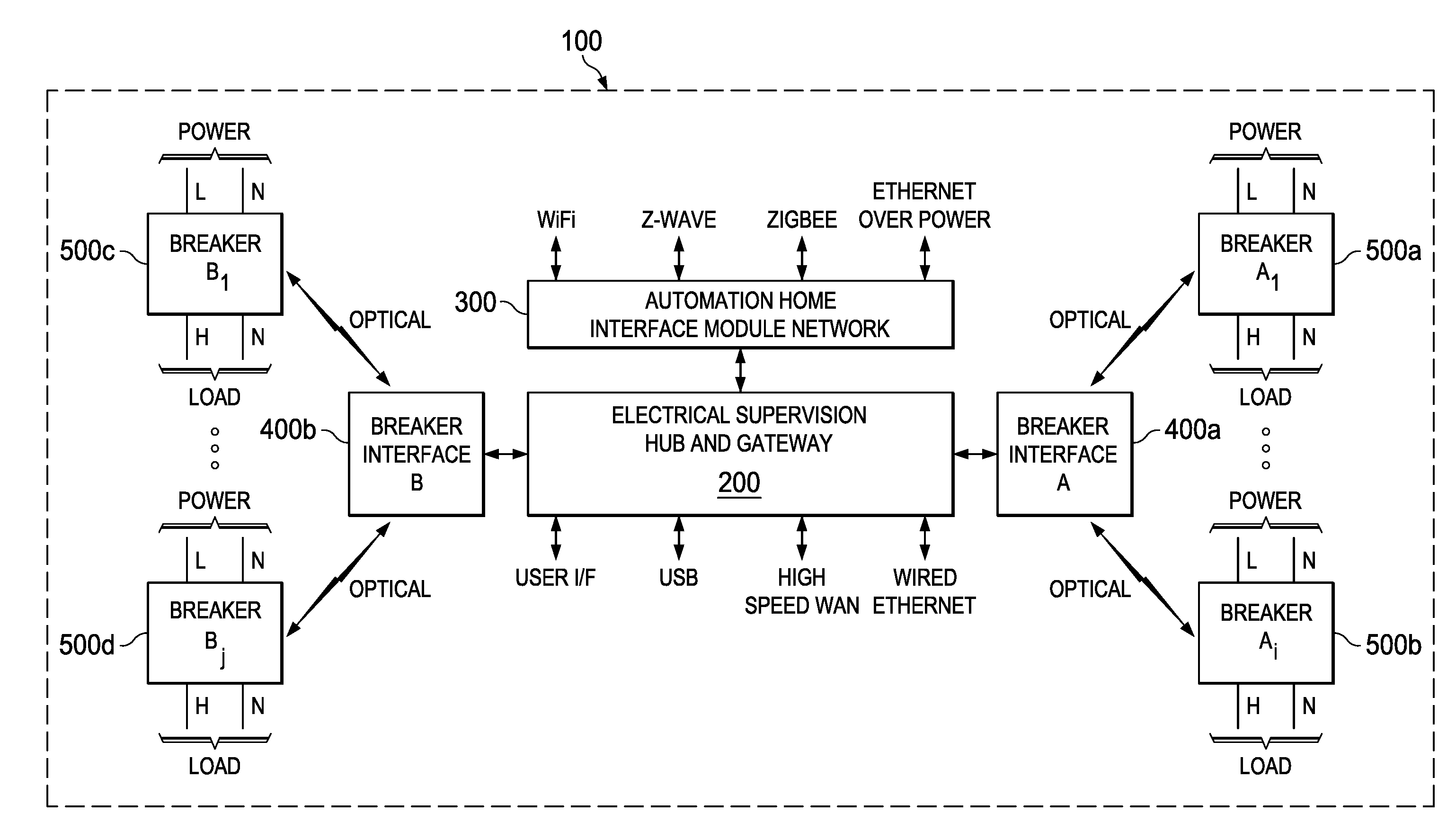
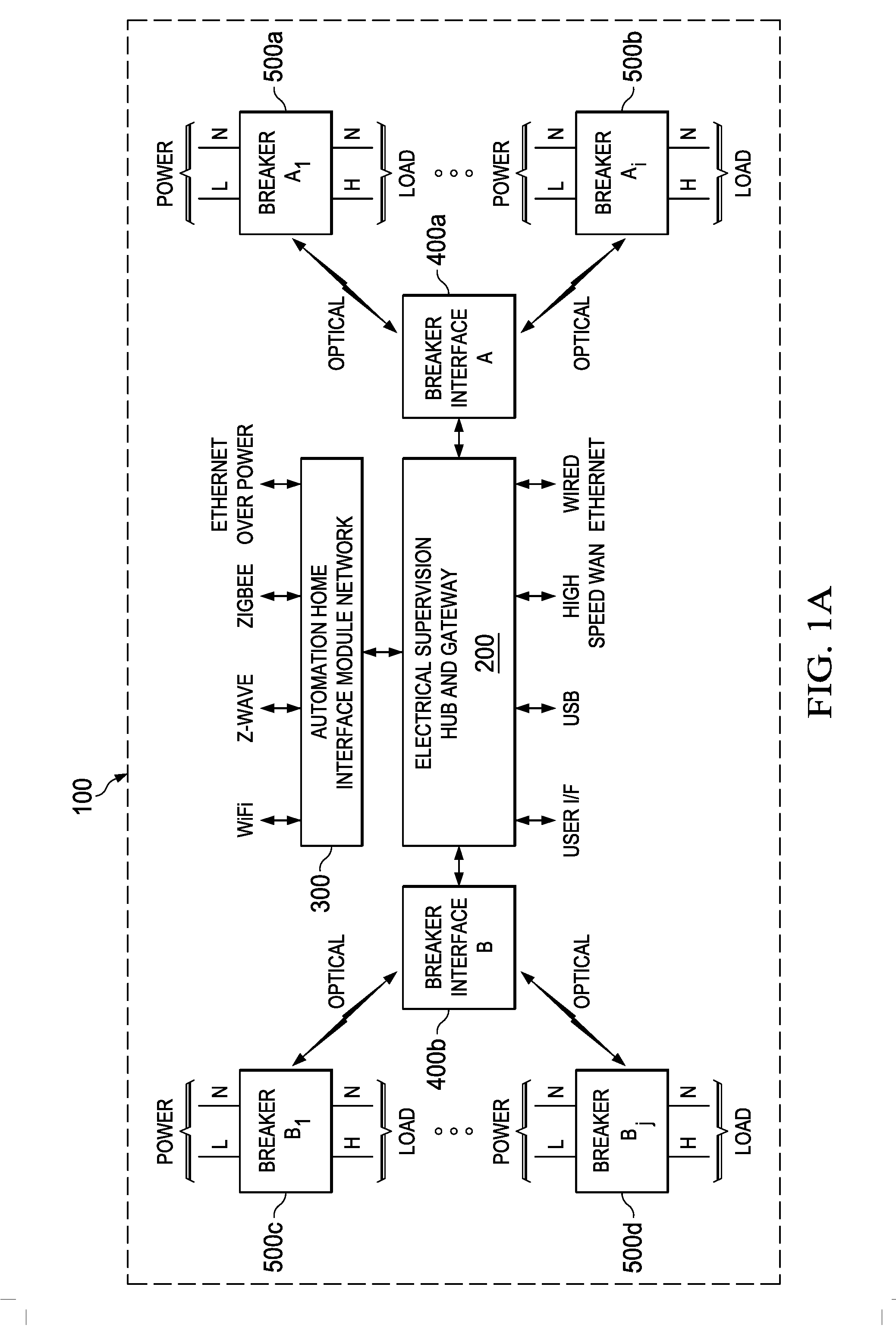
[0040]FIG. 1A is a functional diagram of a preferred electrical circuit breaker and communications system 100 according to one representative embodiment of the principles of the present invention. In the embodiment of FIG. 1A, system 100 is disposed within a single electrical circuit breaker panel, although the present principles are not limited to single-panel configurations.

[0041]System 100 is based on an electrical supervision hub and gateway 200, which communicates with a home automation network (HAN) interface module 300 and a set of breaker interface units 400a-400b. In turn, breaker interface unit 400a (breaker interface A) communicates via optical links with a set of i number of electrical circuit breakers 500 (where i is an integer index), two of which are shown as...


PUM


Abstract

A circuit breaker system integrated into a package including an input for coupling to an external electrical power source, an output for coupling to an external electrical circuit, and a current path selectively coupling the input and the output. A mechanical circuit breaker mechanism interrupts electrical power flow through the current path in response to a current exceeding a predetermined value. A trip solenoid causes the mechanical circuit breaker mechanism to interrupt electrical power flow through current path in response to a control signal. Voltage and current sensors measure voltage and current values of the electrical power flowing through the current path and a microprocessor selectively generates the control signal in response to the measured voltage and current values, along with and a control profile stored in memory, to energize the solenoid and cause the mechanical circuit breaker mechanism to interrupt the electrical power.

Description

CROSS-REFERENCE TO RELATED APPLICATION[0001]The present application claims the benefit of U.S. Provisional Applications Ser. No. 62 / 109,349, filed Jan. 29, 2015, and Ser. No. 62,134,378, filed Mar. 17, 2015, which are incorporated herein by reference for all purposes.FIELD OF INVENTION[0002]The present invention relates in general to electrical circuit breakers and in particular to enhanced circuit breakers and circuit breaker panels and systems and methods using the same.BACKGROUND OF INVENTION[0003]Electrical power systems, such as those commonly found in private residences and offices, present various hazards to both the surrounding structures and their occupants. These hazards can be significant, including fires and electrocution, which sometimes can be fatal. For example, excess loading on a branch circuit within a home can result in the overheating of wires and the potential for fires. Ground faults, which occur when a low-resistance grounding path is broken and electrical cur...

Claims


Application Information

Patent Timeline
04 Aug 2016
Publication
US20160225562A1
IPC
H01H47/00; H01H47/22
CPC
H02H1/0069; H02H1/0092; H02H3/006; H01H47/22; H02H3/10; H02H3/26; H01H47/002; H02H3/08
Inventors
FRANKS, JEFFREY L.; WILLIAMS, STEPHEN E.